


RIoTboard First Impressions
 | A new board was thrown my way touted as the solution for the Internet of Things and a suitable development platform for Android as an alternative to emulation, this was of course the RIoTboard. The box is clean in its design, surprisingly simplistic and also lacking any defined details as to what is inside it, but in a pleasing way. You can see the distinctive logo on the top of the box with its name on the side, though the image of the board itself is somewhat edited and stretched the logo is portraying the typical images of power and wireless connectivity. On the underside of the box are the standard declarations of how not to dispose of the board, along with the stated website (which possibly led you here) RIoTboard.org - the case/capitalisation of the wording being important to the product identity. |
The box isn't difficult to get into, at least not the one I had my hands onto. I'm told that this is the production model of the box which you can now buy (MCIMX6 SOLO - RIOTBOARD | Farnell UKMCIMX6 SOLO - RIOTBOARD | Farnell UK) for the sum of £46.55 Inside we have the board itself in a warming red colour and many, many connectors. Usually connectors are expensive to add onto a development board and it is quite nice that so many are available here. Of note the LVDS connector is not the standard ribbon connector that is usually seen on boards. In the box we also have a USB Type A to USB Mini A cable and a copy of the Quick Start Guide. It may need to be noted for some people that the board cannot be powered from the USB port alone like some other development kits and it requires an external power supply unit. There is no external power supply unit supplied with the board. |
<html><head><title>Jive SBS</title></head> <body><font face="arial,helvetica,sans-serif"> <b>Error</b><br><font size="-1"> An general error occurred while processing your request. </font></font></body></html> |
<html><head><title>Jive SBS</title></head> <body><font face="arial,helvetica,sans-serif"> <b>Error</b><br><font size="-1"> An general error occurred while processing your request. </font></font></body></html> |
In the Quickstart Guide (QSG) I received with the development board, there is an error in that the board requires a 5 volt 4 amp power supply. After some asking around within element14 I discovered that it actually requires 5 volt 1 amp and this has now been reflected in the updated Quickstart Guide (RIoTboard: Quick User Guide for RIoTboard). The main purpose of the QSG is to quickly familiarise yourself with the input/output on the board and to point you towards the element14 community page to find your files and support. |
At the core of the board it uses an ARM Cortex A9 processor, specifically an I.MX 6 Solo, 1Ghz (MCIMX6S5DVM10AB - FREESCALE SEMICONDUCTOR - MPU, I.MX6 SOLO, 1GHZ, 624MAPBGA | Farnell UKMCIMX6S5DVM10AB - FREESCALE SEMICONDUCTOR - MPU, I.MX6 SOLO, 1GHZ, 624MAPBGA | Farnell UK) and it is possible to see the specific capabilities of this processor in the datasheet for the processor (Freescale: Datasheet for i.MX 6Solo/6DualLite Applications Processors for Consumer Products).
Unfortunately although the User Manual states that the processor has PCIe connectivity, this does not appear to be broken out to a connector on the board. The input/output pin block appears to be solely I2c/UART connectivity.
Changing from Android to Ubuntu on Windows
The RIoTboard by default comes with Android Jellybean verison 4.3, there is also a version of Ubuntu available.
After reading the User Manual and acquiring the image files, I became a little confused as to the best steps to take to flash the RIoTboard. Do I copy files over? Why isn't the MFGTool2 program working? Why are the files all over the place? What's going on? So what I'm going to cover, is the steps I took to get this working. I managed it and the board is running the Ubuntu image.
To start with, it helps to take advantage of the UART serial debug port on the RIoTboard, else you're going to struggle to find out what the status of your flash is for certain and whether or not it's working. There's only so much you can garner from the HDMI port after all and this is a good practice to get into.
In sections 2.3.12 and 3.4 of the User Manual (RIoTboard: User Manual for RIoTboard Platform) it attempts to tell you how to connect to the port. The best way, is to use a serial cable such as this one: TTL-232R-RPI - FTDI - CABLE, DEBUG, TTL-232-USB, RPI | Farnell UKTTL-232R-RPI - FTDI - CABLE, DEBUG, TTL-232-USB, RPI | Farnell UK because all you need are the Rx (Receive), Tx (Transmit) and GND (ground) pins to communicate with over USB (there are a lot of these types of cables, Analog / Power / Sensor / Wireless / Lighting Development Kits | Farnell UK | Results but you do not need to connect up a 3.3v or 5v wire).
Once you have your cable connected and plugged into your USB port, you will have to open up device manager:
- For Windows XP: https://www.microsoft.com/resources/documentation/windows/xp/all/proddocs/en-us/snap_dev_mgr.mspx
- For Windows Vista and and above: Opening Device Manager - Microsoft Windows Help
Then check what the COM port is (Listed under 'Ports' typically, or similar name. This is a somewhat legacy naming convention from when we had physical serial COMmunication ports that communicated with devices such as Modems).
Now what we need is software to receive the data. I recommend PuTTy because it's free and you don't need administrative rights to run or install it.
Portable: PuTTY Portable | PortableApps.com - Portable software for USB, portable and cloud drives
Install: PuTTY: a free telnet/ssh client
When you run PuTTy you'll have to setup the COM port (as discovered via device manager instructed above) and also the flow control, data rate, etc:
 |  |
The key settings to take away from here are the "Speed (baud)" and the "Flow control". If there's anything set incorrectly, when you click 'Open' on the "Session" tab you're going to get a garbled mess or unknown characters.
Hopefully what you should get is an output like the following, when you power on the board with it all connected and such:
U-Boot 2009.08-00694-g632a6e0-dirty (Dec 24 2013 - 17:03:32)
CPU: Freescale i.MX6 family TO1.1 at 792 MHz
Thermal sensor with ratio = 186
Temperature: 37 C, calibration data 0x59951c5f
mx6q pll1: 792MHz
mx6q pll2: 528MHz
mx6q pll3: 480MHz
mx6q pll8: 50MHz
ipg clock : 66000000Hz
ipg per clock : 66000000Hz
uart clock : 80000000Hz
cspi clock : 60000000Hz
ahb clock : 132000000Hz
axi clock : 198000000Hz
emi_slow clock: 99000000Hz
ddr clock : 396000000Hz
usdhc1 clock : 198000000Hz
usdhc2 clock : 198000000Hz
usdhc3 clock : 198000000Hz
usdhc4 clock : 198000000Hz
nfc clock : 24000000Hz
Board: i.MX6DL/Solo-SABRESD: unknown-board Board: 0x61011 [POR ]
Boot Device: MMC
I2C: ready
DRAM: 1 GB
MMC: FSL_USDHC: 0,FSL_USDHC: 1,FSL_USDHC: 2,FSL_USDHC: 3
*** Warning - bad CRC or MMC, using default environment
In: serial
Out: serial
Err: serial
Net: got MAC address from IIM: 00:00:00:00:00:00
This is just a snapshot of the text, if you really want to you can read an entire standard boot using Android here: RIoTboard Serial Dump with Android - Pastebin.com
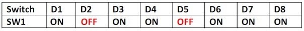
Now with the RIoTboard turned off, we need to set the DIP switches, according to section 4.1 of the User Manual, we set it to "Serial Download Mode":
 | There's one final setup step and that's to connect the USB cable which came with the board.
Confusingly there are two Mini-A USB ports on the RIoTboard, one has a specific function in that it functions for OpenSDA. The port we're interested in is sat between the MicroSD and Ethernet (RJ45) port on the board, which if you look at the RIoTboard image explaining the DIP switches, is in the top right of the board, next to where you connect the debug serial cable. Once these are connected you'll need to turn on your RIoTboard. Grab the image! If you haven't already done so, download the Linux image that we're going to write/flash to the RIoTboard (http://downloads.element14.com/linux/Linux.zip?ICID=knode-riotboard-quick&COM=RIoTboard ) and extract it (7Zip is a good, free tool for this). |
Once extracted you will now have a folder called 'Linux'. You're interested in the tool located in:
- Linux\tools\Mfgtools-Rel-4.1.0_130816_MX6DL_UPDATER
You now need to rename the following file:
- Linux\tools\Mfgtools-Rel-4.1.0_130816_MX6DL_UPDATER\Profiles\MX6DL Linux Update\OS Firmware\ucl2.txt
To be called:
- Linux\tools\Mfgtools-Rel-4.1.0_130816_MX6DL_UPDATER\Profiles\MX6DL Linux Update\OS Firmware\ucl2.xml
This file contains the profile details for each board that MFGTools supports. The User Manual would have you believe that now you need to copy over files from:
- Linux\image_SVN2487
into
- Linux\tools\Mfgtools-Rel-4.1.0_130816_MX6DL_UPDATER\Profiles\MX6DL Linux Update\OS Firmware
In my experience this didn't do much, in fact I would hazard a suggestion that it has already been done in the files. Feel free to do this step if you wish, it won't harm anything. However in the file:
- Linux\tools\Mfgtools-Rel-4.1.0_130816_MX6DL_UPDATER\cfg.ini
It helps to target the onboard flash that we're going to update. My cfg.ini looked like this:
[profiles]
chip = MX6DL Linux Update
[platform]
board = RIOT
[LIST]
name = i.MX6SOLO-ubuntu-RIOT-eMMC
So with your serial PuTTy session running and the USB connected to the correct port, run MFGTool2 and you should be presented with a message in one of the text boxes that a "HID-compliant device" is connected. If there are any problems it will show "No Device Connected" and you will have to make sure that the RIoTboard DIP switches are set properly, the USB cable/port on your computer works and it is setup properly in Device Manager.
If all's well, click Start! You should be able to see its progress in Windows and also on the board via PuTTy. While flashing the device I had a message on the PuTTy terminal saying I had to power cycle the board before it would continue. I unplugged and re-connected the board to the power and the flashing continued.
If anything goes wrong, just start again.
Note: Don't forget to set your DIP switches back after flashing, while the board is turned off so that it boots properly:
Hope this helps, if there are any errors or if you have observations/feedback, or if this worked for you or didn't work, let me know.
Thanks for reading.

Top Comments