


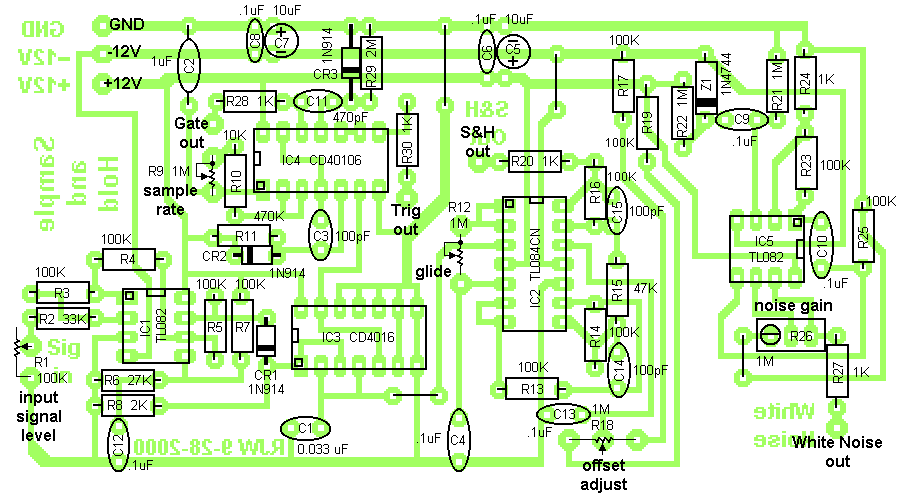
I would like to publish parts placement diagrams like this to make stuffing easier. (This diagram was made by Ray Wilson / MusicFromOuterSpace.com)
I would like to publish parts placement diagrams like this to make stuffing easier. (This diagram was made by Ray Wilson / MusicFromOuterSpace.com)