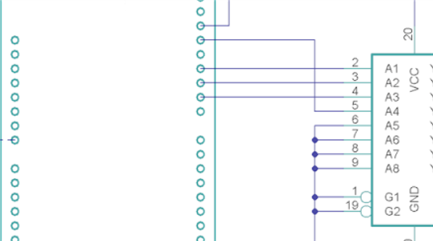
Greetings,
I am designing a vessel monitoring system - think of it as Internet of Boat. Lots of sensors for temperature, AC/DC voltage/current, humidity, security, water levels, fuel levels, etc. Their will be three nodes wirelessly communicating between the vessel's compartments and then sending information to the cloud. This will be a "one off" so no taking it to a circuit board, however, I do want to document the schematic. I started with Fritzing but found the lack of library elements and a few other issues constraining so I moved to Kicad but again, ran into lack of schematic library parts. The more I read, it seemed folks were using Eagle so I dove in.
I know this is more of a system interconnect diagram but am hopeful Eagle's schematic capability will allow me to document it.
I will be using some arduino/shield combination but am not sure how to represent a "stacked assembly" showing which connections in the headers are actually used for signaling so that I don't inadvertently connect another item to an already used pin. For instance, an arduino uno and an ethernet shield - I was thinking of having library elements for the arduino and ethernet shield next to each other on the schematic and then just wire the appropriate signals. I would not place connections between the "unused" header pins so as to keep the schematic clean.
I would like some expert guidance before going too far down the path only to find I've screwed something up and have to start over. I've search but have not come up with an answer so hopefully someone can help.