element14 Community
element14 Community
    Register Log In
  • Site
  • Search
  • Log In Register
  • Community Hub
    Community Hub
    • What's New on element14
    • Feedback and Support
    • Benefits of Membership
    • Personal Blogs
    • Members Area
    • Achievement Levels
  • Learn
    Learn
    • Ask an Expert
    • eBooks
    • element14 presents
    • Learning Center
    • Tech Spotlight
    • STEM Academy
    • Webinars, Training and Events
    • Learning Groups
  • Technologies
    Technologies
    • 3D Printing
    • FPGA
    • Industrial Automation
    • Internet of Things
    • Power & Energy
    • Sensors
    • Technology Groups
  • Challenges & Projects
    Challenges & Projects
    • Design Challenges
    • element14 presents Projects
    • Project14
    • Arduino Projects
    • Raspberry Pi Projects
    • Project Groups
  • Products
    Products
    • Arduino
    • Avnet & Tria Boards Community
    • Dev Tools
    • Manufacturers
    • Multicomp Pro
    • Product Groups
    • Raspberry Pi
    • RoadTests & Reviews
  • About Us
    About the element14 Community
  • Store
    Store
    • Visit Your Store
    • Choose another store...
      • Europe
      •  Austria (German)
      •  Belgium (Dutch, French)
      •  Bulgaria (Bulgarian)
      •  Czech Republic (Czech)
      •  Denmark (Danish)
      •  Estonia (Estonian)
      •  Finland (Finnish)
      •  France (French)
      •  Germany (German)
      •  Hungary (Hungarian)
      •  Ireland
      •  Israel
      •  Italy (Italian)
      •  Latvia (Latvian)
      •  
      •  Lithuania (Lithuanian)
      •  Netherlands (Dutch)
      •  Norway (Norwegian)
      •  Poland (Polish)
      •  Portugal (Portuguese)
      •  Romania (Romanian)
      •  Russia (Russian)
      •  Slovakia (Slovak)
      •  Slovenia (Slovenian)
      •  Spain (Spanish)
      •  Sweden (Swedish)
      •  Switzerland(German, French)
      •  Turkey (Turkish)
      •  United Kingdom
      • Asia Pacific
      •  Australia
      •  China
      •  Hong Kong
      •  India
      •  Japan
      •  Korea (Korean)
      •  Malaysia
      •  New Zealand
      •  Philippines
      •  Singapore
      •  Taiwan
      •  Thailand (Thai)
      •  Vietnam
      • Americas
      •  Brazil (Portuguese)
      •  Canada
      •  Mexico (Spanish)
      •  United States
      Can't find the country/region you're looking for? Visit our export site or find a local distributor.
  • Translate
  • Profile
  • Settings
Autodesk EAGLE
  • Products
  • More
Autodesk EAGLE
EAGLE User Support (English) Grounding a HTSSOP DAP chip
  • Blog
  • Forum
  • Documents
  • Events
  • Polls
  • Files
  • Members
  • Mentions
  • Sub-Groups
  • Tags
  • More
  • Cancel
  • New
Join Autodesk EAGLE to participate - click to join for free!
Actions
  • Share
  • More
  • Cancel
Forum Thread Details
  • Replies 3 replies
  • Subscribers 188 subscribers
  • Views 697 views
  • Users 0 members are here
Related

Grounding a HTSSOP DAP chip

e14 Contributor
e14 Contributor over 13 years ago

Hi,

I am interested in using a Texas Instruments led driver in a project. Eagle

has a part that I can use (HTSSOP38DAP footprint) found in the Texas

instruments library (texas.lbr). However, even after some concerted

attempts, I am uncertain how to connect the PTH on the part to my ground

plane. I would appreciate any suggestions, guidance, or pointers me to

documentation to help me out.


Having fun learning the ins and outs of Eagle,

Thanks in advance,

Shiva

--

Web access to CadSoft support forums at www.eaglecentral.ca.  Where the CadSoft EAGLE community meets.


  • Sign in to reply
  • Cancel
Parents
  • e14 Contributor
    e14 Contributor over 13 years ago

    Hi Shiva,


    I worked with one TI LED driver recently. In the chip's datasheet I didn't find any request/recommendation/etc. that the thermal pad is to be connected to the ground plane. They are specifying just the cases when the thermal pad is soldered or not to "floating" copper area.


    Nevertheless, If you'd like to solder it to a ground plane, you have to modify the library first. In the Library editor open the related library and then:

    1) Open your driver chip as symbol and add a new pin (name it THERMAL, for example).

    2) Open your driver chip as a device and click Connect button.

    3) Link your new THERMAL pin with (probably named) EXP pad.

    4) Save the library.


    In the Schematic editor open your schematics file and:

    1) Click Library -> Update All option.

    2) Connect new THERMAL pin to the ground.


    You are now ready to route thermal pad in the Board editor...


    Best wishes,  Ivan.

    • Cancel
    • Vote Up 0 Vote Down
    • Sign in to reply
    • Cancel
Reply
  • e14 Contributor
    e14 Contributor over 13 years ago

    Hi Shiva,


    I worked with one TI LED driver recently. In the chip's datasheet I didn't find any request/recommendation/etc. that the thermal pad is to be connected to the ground plane. They are specifying just the cases when the thermal pad is soldered or not to "floating" copper area.


    Nevertheless, If you'd like to solder it to a ground plane, you have to modify the library first. In the Library editor open the related library and then:

    1) Open your driver chip as symbol and add a new pin (name it THERMAL, for example).

    2) Open your driver chip as a device and click Connect button.

    3) Link your new THERMAL pin with (probably named) EXP pad.

    4) Save the library.


    In the Schematic editor open your schematics file and:

    1) Click Library -> Update All option.

    2) Connect new THERMAL pin to the ground.


    You are now ready to route thermal pad in the Board editor...


    Best wishes,  Ivan.

    • Cancel
    • Vote Up 0 Vote Down
    • Sign in to reply
    • Cancel
Children
  • e14 Contributor
    e14 Contributor over 13 years ago in reply to e14 Contributor

    Hello Ivan,

    Thank you very much for the detailed steps.  I appreciate it!  It all seems to work, but with a few small hiccups. If you have a few more moments perhaps you can give me your feedback on one remaining issue.


    I followed you instructions, but because my ground polygon in on the bottom layer:

    1. I added a bottom layer SMD to my driver chip package.

    2. I named this bottom layer EXP2 (the top one is named EXP as you thought), and

    3. After opening my driver chip as a device, I connected the THERMAL pin to EXP2 pad.


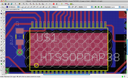
    I want to tie the THERMAL pin to the bottom layer ground polygon. Below is a snapshot of the the TLC on my board. My question is why is my polygon (named GND, and which I would like to merge with the EXP2 pad) prevented from extending under the chip? I can create a wire to extend from EXP2 and the ground polygon (you can just make out the ratsnest wire from pin 33), but somehow the polygon itself is kept out.


    Best Regards,

    Shiva

    PS I'm using a TLC5951. The datasheet suggests connecting the thermal pad to the ground plane to help dissipate more heat.


    image

    • Cancel
    • Vote Up 0 Vote Down
    • Sign in to reply
    • Cancel
element14 Community

element14 is the first online community specifically for engineers. Connect with your peers and get expert answers to your questions.

  • Members
  • Learn
  • Technologies
  • Challenges & Projects
  • Products
  • Store
  • About Us
  • Feedback & Support
  • FAQs
  • Terms of Use
  • Privacy Policy
  • Legal and Copyright Notices
  • Sitemap
  • Cookies

An Avnet Company © 2026 Premier Farnell Limited. All Rights Reserved.

Premier Farnell Ltd, registered in England and Wales (no 00876412), registered office: Farnell House, Forge Lane, Leeds LS12 2NE.

Follow element14

  • X
  • Facebook
  • linkedin
  • YouTube