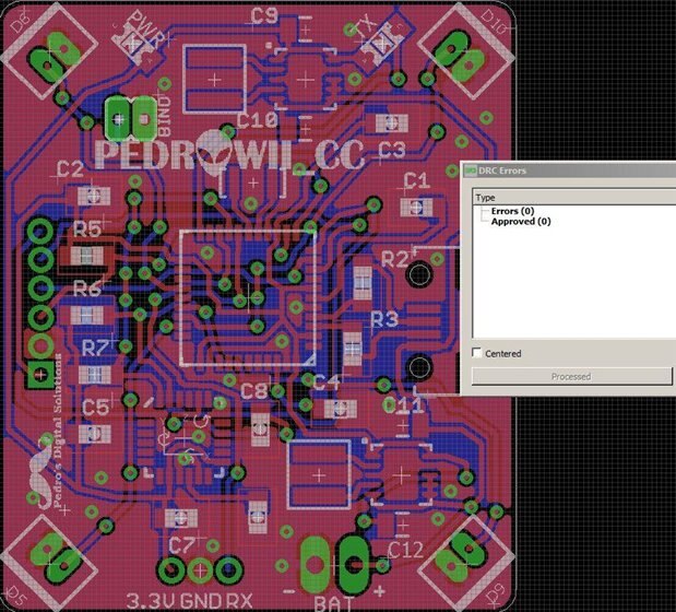
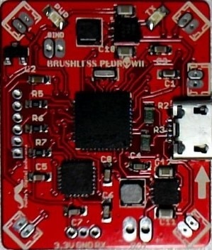
I am in the process of redesigning my quadcopter flight control board from running brushed to brushless motors . This necessitated me adding a 5v buck boost regulator and some other minor changes as well as completely relocating or re-orientating virtually every component on the board. As you can no doubt tell from my board layout I am a novice when it comes to PCB routing but I have done the best that I can so far. The circuit is proven so it is just a matter of finalising the routing so I can get some test PCB's made and build them out at home which I am completely comfortable and experienced at doing.
Even with the first successful brushed version of this board the Iteadstudio DRC would flag clearance errors on the Atmega, MPU6050, and Molex connectors and this has not proved to be an issue as I have made around twenty of these boards with no issues and they perform flawlessly.
With this in mind I am wary of believing some clearance issues being flagged by the DRC on this board but would just like someone to cast an eye over what I have done and point out any glaringly obvious omissions or mistakes that may stop the board from functioning from what they can see. Being a novice I realise that a seasoned professional would make a much more elegant job of the routing but I am not after perfection or anything close to it, just something that will work and that I can hand assemble. When I run rats nest I can see a lot of un-routed airwires but if I run a "run length ulp" it only shows two un-routed wires. I have not checked through all the clearance errors but as I said the only ones that I would be concerned with are trace to trace and/or via clearances.
Thank you for any help or advice of a constructive nature and thanks for your time,
Pedro