element14 Community
element14 Community
    Register Log In
  • Site
  • Search
  • Log In Register
  • Community Hub
    Community Hub
    • What's New on element14
    • Feedback and Support
    • Benefits of Membership
    • Personal Blogs
    • Members Area
    • Achievement Levels
  • Learn
    Learn
    • Ask an Expert
    • eBooks
    • element14 presents
    • Learning Center
    • Tech Spotlight
    • STEM Academy
    • Webinars, Training and Events
    • Learning Groups
  • Technologies
    Technologies
    • 3D Printing
    • FPGA
    • Industrial Automation
    • Internet of Things
    • Power & Energy
    • Sensors
    • Technology Groups
  • Challenges & Projects
    Challenges & Projects
    • Design Challenges
    • element14 presents Projects
    • Project14
    • Arduino Projects
    • Raspberry Pi Projects
    • Project Groups
  • Products
    Products
    • Arduino
    • Avnet & Tria Boards Community
    • Dev Tools
    • Manufacturers
    • Multicomp Pro
    • Product Groups
    • Raspberry Pi
    • RoadTests & Reviews
  • About Us
  • Store
    Store
    • Visit Your Store
    • Choose another store...
      • Europe
      •  Austria (German)
      •  Belgium (Dutch, French)
      •  Bulgaria (Bulgarian)
      •  Czech Republic (Czech)
      •  Denmark (Danish)
      •  Estonia (Estonian)
      •  Finland (Finnish)
      •  France (French)
      •  Germany (German)
      •  Hungary (Hungarian)
      •  Ireland
      •  Israel
      •  Italy (Italian)
      •  Latvia (Latvian)
      •  
      •  Lithuania (Lithuanian)
      •  Netherlands (Dutch)
      •  Norway (Norwegian)
      •  Poland (Polish)
      •  Portugal (Portuguese)
      •  Romania (Romanian)
      •  Russia (Russian)
      •  Slovakia (Slovak)
      •  Slovenia (Slovenian)
      •  Spain (Spanish)
      •  Sweden (Swedish)
      •  Switzerland(German, French)
      •  Turkey (Turkish)
      •  United Kingdom
      • Asia Pacific
      •  Australia
      •  China
      •  Hong Kong
      •  India
      •  Korea (Korean)
      •  Malaysia
      •  New Zealand
      •  Philippines
      •  Singapore
      •  Taiwan
      •  Thailand (Thai)
      • Americas
      •  Brazil (Portuguese)
      •  Canada
      •  Mexico (Spanish)
      •  United States
      Can't find the country/region you're looking for? Visit our export site or find a local distributor.
  • Translate
  • Profile
  • Settings
Autodesk EAGLE
  • Products
  • More
Autodesk EAGLE
EAGLE User Support (English) Irregular smd pad shapes
  • Blog
  • Forum
  • Documents
  • Events
  • Polls
  • Files
  • Members
  • Mentions
  • Sub-Groups
  • Tags
  • More
  • Cancel
  • New
Join Autodesk EAGLE to participate - click to join for free!
Actions
  • Share
  • More
  • Cancel
Forum Thread Details
  • State Not Answered
  • Replies 1 reply
  • Subscribers 178 subscribers
  • Views 863 views
  • Users 0 members are here
Related

Irregular smd pad shapes

btmcmahan
btmcmahan over 8 years ago

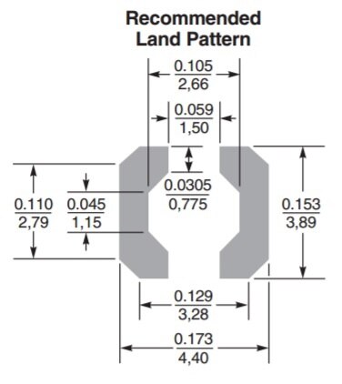
Okay, I've been using Eagle for a while now, but I just encountered a new challenge.  I have this inductor.  It has an irregular pad footprint.  So...how do I make an irregular shaped (SMD) pad?

I know make my own "DIY Pad" by drawing a polygon on the top layer.  And I can make a second polygon on the tCream layer.  And I can make a third slightly larger polygon for the tStop layer.  But since this isn't a "recognized" pad, how do I make the connection between my symbol & package inside the device window?


Am I overthinking this?  Is there some obvious solution I am missing?

image

  • Sign in to reply
  • Cancel
Parents
  • autodeskguest
    0 autodeskguest over 8 years ago

    On 1/04/2017 10:54 a.m., Brandon McMahan wrote:

    Okay, I've been using Eagle for a while now, but I just encountered a new challenge.  I have this inductor.  It has an irregular pad footprint.  So...how do I make an irregular shaped (SMD) pad?

    I know make my own "DIY Pad" by drawing a polygon on the top layer.  And I can make a second polygon on the tCream layer.  And I can make a third slightly larger polygon for the tStop layer.  But since this isn't a "recognized" pad, how do I make the connection between my symbol & package inside the device window?


    Am I overthinking this?  Is there some obvious solution I am missing?


    If you have version 6 or later

    See "Help/Editor Commands/PAD|SMD/Arbitrary Pad Shapes"


    It is similar to what you appear to have been doing. The library package

    needs to contain an SMD or Pad which is the connection point for the

    signal but the surrounding polygon or wire (all done in the package

    editor) is permitted and you don't get DRC errors later. The tStop and

    tCream still need to be created manually, in the package editor.


    HTH

    Warren


    --

    ... use NNTP://news.cadsoft.de and a functional news reader like

    Thunderbird!

    ... or http://www.eaglecentral.ca browser access to CadSoft EAGLE

    support forums.


    ---

    This email has been checked for viruses by Avast antivirus software.

    https://www.avast.com/antivirus


    • Cancel
    • Vote Up 0 Vote Down
    • Sign in to reply
    • Verify Answer
    • Cancel
Reply
  • autodeskguest
    0 autodeskguest over 8 years ago

    On 1/04/2017 10:54 a.m., Brandon McMahan wrote:

    Okay, I've been using Eagle for a while now, but I just encountered a new challenge.  I have this inductor.  It has an irregular pad footprint.  So...how do I make an irregular shaped (SMD) pad?

    I know make my own "DIY Pad" by drawing a polygon on the top layer.  And I can make a second polygon on the tCream layer.  And I can make a third slightly larger polygon for the tStop layer.  But since this isn't a "recognized" pad, how do I make the connection between my symbol & package inside the device window?


    Am I overthinking this?  Is there some obvious solution I am missing?


    If you have version 6 or later

    See "Help/Editor Commands/PAD|SMD/Arbitrary Pad Shapes"


    It is similar to what you appear to have been doing. The library package

    needs to contain an SMD or Pad which is the connection point for the

    signal but the surrounding polygon or wire (all done in the package

    editor) is permitted and you don't get DRC errors later. The tStop and

    tCream still need to be created manually, in the package editor.


    HTH

    Warren


    --

    ... use NNTP://news.cadsoft.de and a functional news reader like

    Thunderbird!

    ... or http://www.eaglecentral.ca browser access to CadSoft EAGLE

    support forums.


    ---

    This email has been checked for viruses by Avast antivirus software.

    https://www.avast.com/antivirus


    • Cancel
    • Vote Up 0 Vote Down
    • Sign in to reply
    • Verify Answer
    • Cancel
Children
No Data
element14 Community

element14 is the first online community specifically for engineers. Connect with your peers and get expert answers to your questions.

  • Members
  • Learn
  • Technologies
  • Challenges & Projects
  • Products
  • Store
  • About Us
  • Feedback & Support
  • FAQs
  • Terms of Use
  • Privacy Policy
  • Legal and Copyright Notices
  • Sitemap
  • Cookies

An Avnet Company © 2025 Premier Farnell Limited. All Rights Reserved.

Premier Farnell Ltd, registered in England and Wales (no 00876412), registered office: Farnell House, Forge Lane, Leeds LS12 2NE.

ICP 备案号 10220084.

Follow element14

  • X
  • Facebook
  • linkedin
  • YouTube