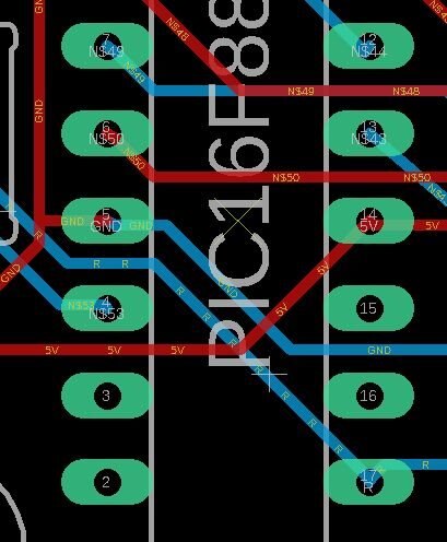
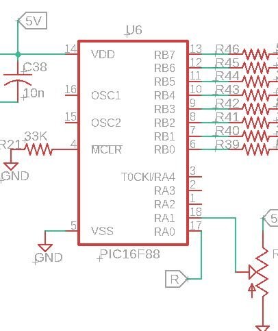
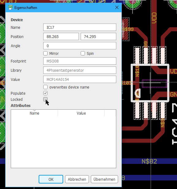
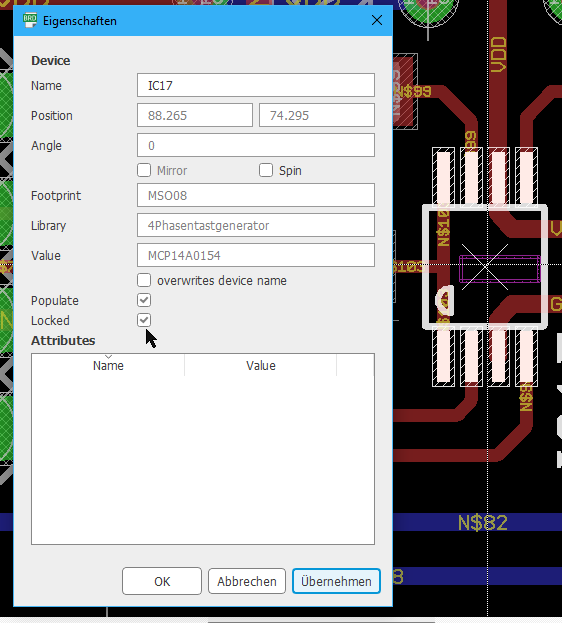
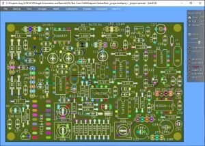
I am somewhat new to Eagle. I have a board which is finished except when I ran the cam processor and view the resulting board, one of the component outlines was missing.The board was fine otherwise. When I went back to edit the board and schematic to try to correct the problem, I found that the part origin was an X rather than a + and I could not select or do anything with the part on the board. I am using version 9.4.2