element14 Community
element14 Community
    Register Log In
  • Site
  • Search
  • Log In Register
  • About Us
  • Community Hub
    Community Hub
    • What's New on element14
    • Feedback and Support
    • Benefits of Membership
    • Personal Blogs
    • Members Area
    • Achievement Levels
  • Learn
    Learn
    • Ask an Expert
    • eBooks
    • element14 presents
    • Learning Center
    • Tech Spotlight
    • STEM Academy
    • Webinars, Training and Events
    • Learning Groups
  • Technologies
    Technologies
    • 3D Printing
    • FPGA
    • Industrial Automation
    • Internet of Things
    • Power & Energy
    • Sensors
    • Technology Groups
  • Challenges & Projects
    Challenges & Projects
    • Design Challenges
    • element14 presents Projects
    • Project14
    • Arduino Projects
    • Raspberry Pi Projects
    • Project Groups
  • Products
    Products
    • Arduino
    • Avnet Boards Community
    • Dev Tools
    • Manufacturers
    • Multicomp Pro
    • Product Groups
    • Raspberry Pi
    • RoadTests & Reviews
  • Store
    Store
    • Visit Your Store
    • Choose another store...
      • Europe
      •  Austria (German)
      •  Belgium (Dutch, French)
      •  Bulgaria (Bulgarian)
      •  Czech Republic (Czech)
      •  Denmark (Danish)
      •  Estonia (Estonian)
      •  Finland (Finnish)
      •  France (French)
      •  Germany (German)
      •  Hungary (Hungarian)
      •  Ireland
      •  Israel
      •  Italy (Italian)
      •  Latvia (Latvian)
      •  
      •  Lithuania (Lithuanian)
      •  Netherlands (Dutch)
      •  Norway (Norwegian)
      •  Poland (Polish)
      •  Portugal (Portuguese)
      •  Romania (Romanian)
      •  Russia (Russian)
      •  Slovakia (Slovak)
      •  Slovenia (Slovenian)
      •  Spain (Spanish)
      •  Sweden (Swedish)
      •  Switzerland(German, French)
      •  Turkey (Turkish)
      •  United Kingdom
      • Asia Pacific
      •  Australia
      •  China
      •  Hong Kong
      •  India
      •  Korea (Korean)
      •  Malaysia
      •  New Zealand
      •  Philippines
      •  Singapore
      •  Taiwan
      •  Thailand (Thai)
      • Americas
      •  Brazil (Portuguese)
      •  Canada
      •  Mexico (Spanish)
      •  United States
      Can't find the country/region you're looking for? Visit our export site or find a local distributor.
  • Translate
  • Profile
  • Settings
Autodesk EAGLE
  • Products
  • More
Autodesk EAGLE
EAGLE User Support (English) First PCB order. Requesting Advice on Electrical Schematic.
  • Blog
  • Forum
  • Documents
  • Events
  • Polls
  • Files
  • Members
  • Mentions
  • Sub-Groups
  • Tags
  • More
  • Cancel
  • New
Join Autodesk EAGLE to participate - click to join for free!
Actions
  • Share
  • More
  • Cancel
Forum Thread Details
  • State Suggested Answer
  • Replies 9 replies
  • Answers 2 answers
  • Subscribers 176 subscribers
  • Views 862 views
  • Users 0 members are here
  • first
  • pcb
Related

First PCB order. Requesting Advice on Electrical Schematic.

Former Member
Former Member over 10 years ago

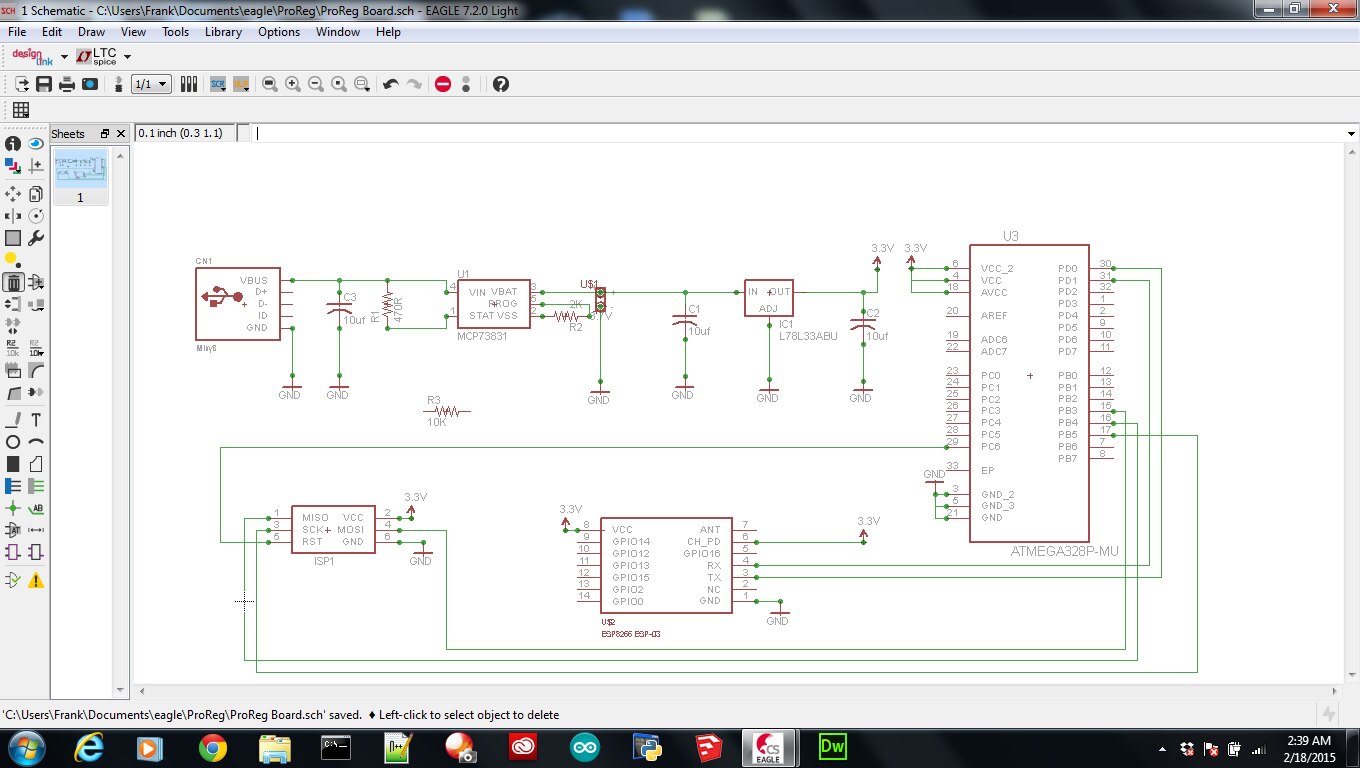
Other than the 10K Resistor that is not connected to anything, I am wondering if anyone can spot any issues with the schematic below?


image

  • Sign in to reply
  • Cancel
Parents
  • michaelkellett
    0 michaelkellett over 10 years ago

    The 78L33 is not a suitable regulator for this application - you are taking power from a USB connector using only the power pins (itself rather bad practice) so you supply voltage may be as low as 4.5V according to specs but down to 4V in real life. The &*L33 (page 4 of ST's data sheet) has a dropout voltage (max) of 1.7V so it needs a supply of at least 5.03V to remain in regulation. Change the 78L33 for a modern low drop regulator.

    You have no small ceramic caps across the supply to the processor - add a 0.1uF ceramic cap to ground for each VCC pin on the processor. They must be placed close to the processor pins. You need similar caps for ISP1.


    The ESP8266 will need more decoupling - are you using  a ready made module or a bare chip. Don't use the bare chip unless you have access to, and know how to use RF test gear.

    I would expect  a WiFi chip to draw quite large peak currents - on the little module using this chip they use  a much beefier regulator than you have. Check out circuits on the web for these modules and ask yourself why yours is so different.


    MK

    • Cancel
    • Vote Up 0 Vote Down
    • Sign in to reply
    • Verify Answer
    • Cancel
  • Former Member
    0 Former Member over 10 years ago in reply to michaelkellett

    MK,


    Thank you for the insight. I will work on sourcing a better voltage regulator (any suggestions?) as well as adding filters to my ATmega328P-MU, ESP8266, and the 6 AVR pins. Could you shed some insight on what you would do to not take power directly from the power pins of the USB connector as you indicate is bad practice? 


    For clarification, the battery terminal is attached to a 3.7V 500mAh lithium ion polymer battery. I am currently using the ready made ESP8266 version 3, but I also have version 7 and 12 that I am tinkering with. I put the voltage regulator in the circuit because the ESP8266 is only rated for 3.3V, but I see what you mean as the ESP8266 will probably draw 300mA at peak, and the 78L33 is only rated for 100mA.


    Because the battery nominal voltage is 3.7V, do you think I can get away with removing the voltage regulator altogether? (i.e. How much less time do you think the chip will last? I have seen the ESP8266 work at 5V.)   


    Thanks Again


    Frank Vigilante

    • Cancel
    • Vote Up 0 Vote Down
    • Sign in to reply
    • Verify Answer
    • Cancel
Reply
  • Former Member
    0 Former Member over 10 years ago in reply to michaelkellett

    MK,


    Thank you for the insight. I will work on sourcing a better voltage regulator (any suggestions?) as well as adding filters to my ATmega328P-MU, ESP8266, and the 6 AVR pins. Could you shed some insight on what you would do to not take power directly from the power pins of the USB connector as you indicate is bad practice? 


    For clarification, the battery terminal is attached to a 3.7V 500mAh lithium ion polymer battery. I am currently using the ready made ESP8266 version 3, but I also have version 7 and 12 that I am tinkering with. I put the voltage regulator in the circuit because the ESP8266 is only rated for 3.3V, but I see what you mean as the ESP8266 will probably draw 300mA at peak, and the 78L33 is only rated for 100mA.


    Because the battery nominal voltage is 3.7V, do you think I can get away with removing the voltage regulator altogether? (i.e. How much less time do you think the chip will last? I have seen the ESP8266 work at 5V.)   


    Thanks Again


    Frank Vigilante

    • Cancel
    • Vote Up 0 Vote Down
    • Sign in to reply
    • Verify Answer
    • Cancel
Children
No Data
element14 Community

element14 is the first online community specifically for engineers. Connect with your peers and get expert answers to your questions.

  • Members
  • Learn
  • Technologies
  • Challenges & Projects
  • Products
  • Store
  • About Us
  • Feedback & Support
  • FAQs
  • Terms of Use
  • Privacy Policy
  • Legal and Copyright Notices
  • Sitemap
  • Cookies

An Avnet Company © 2025 Premier Farnell Limited. All Rights Reserved.

Premier Farnell Ltd, registered in England and Wales (no 00876412), registered office: Farnell House, Forge Lane, Leeds LS12 2NE.

ICP 备案号 10220084.

Follow element14

  • X
  • Facebook
  • linkedin
  • YouTube