element14 Community
element14 Community
    Register Log In
  • Site
  • Search
  • Log In Register
  • About Us
  • Community Hub
    Community Hub
    • What's New on element14
    • Feedback and Support
    • Benefits of Membership
    • Personal Blogs
    • Members Area
    • Achievement Levels
  • Learn
    Learn
    • Ask an Expert
    • eBooks
    • element14 presents
    • Learning Center
    • Tech Spotlight
    • STEM Academy
    • Webinars, Training and Events
    • Learning Groups
  • Technologies
    Technologies
    • 3D Printing
    • FPGA
    • Industrial Automation
    • Internet of Things
    • Power & Energy
    • Sensors
    • Technology Groups
  • Challenges & Projects
    Challenges & Projects
    • Design Challenges
    • element14 presents Projects
    • Project14
    • Arduino Projects
    • Raspberry Pi Projects
    • Project Groups
  • Products
    Products
    • Arduino
    • Avnet Boards Community
    • Dev Tools
    • Manufacturers
    • Multicomp Pro
    • Product Groups
    • Raspberry Pi
    • RoadTests & Reviews
  • Store
    Store
    • Visit Your Store
    • Choose another store...
      • Europe
      •  Austria (German)
      •  Belgium (Dutch, French)
      •  Bulgaria (Bulgarian)
      •  Czech Republic (Czech)
      •  Denmark (Danish)
      •  Estonia (Estonian)
      •  Finland (Finnish)
      •  France (French)
      •  Germany (German)
      •  Hungary (Hungarian)
      •  Ireland
      •  Israel
      •  Italy (Italian)
      •  Latvia (Latvian)
      •  
      •  Lithuania (Lithuanian)
      •  Netherlands (Dutch)
      •  Norway (Norwegian)
      •  Poland (Polish)
      •  Portugal (Portuguese)
      •  Romania (Romanian)
      •  Russia (Russian)
      •  Slovakia (Slovak)
      •  Slovenia (Slovenian)
      •  Spain (Spanish)
      •  Sweden (Swedish)
      •  Switzerland(German, French)
      •  Turkey (Turkish)
      •  United Kingdom
      • Asia Pacific
      •  Australia
      •  China
      •  Hong Kong
      •  India
      •  Korea (Korean)
      •  Malaysia
      •  New Zealand
      •  Philippines
      •  Singapore
      •  Taiwan
      •  Thailand (Thai)
      • Americas
      •  Brazil (Portuguese)
      •  Canada
      •  Mexico (Spanish)
      •  United States
      Can't find the country/region you're looking for? Visit our export site or find a local distributor.
  • Translate
  • Profile
  • Settings
Autodesk EAGLE
  • Products
  • More
Autodesk EAGLE
EAGLE User Support (English) Eagle CAD Non-circle through hole pads?
  • Blog
  • Forum
  • Documents
  • Events
  • Polls
  • Files
  • Members
  • Mentions
  • Sub-Groups
  • Tags
  • More
  • Cancel
  • New
Join Autodesk EAGLE to participate - click to join for free!
Actions
  • Share
  • More
  • Cancel
Forum Thread Details
  • State Verified Answer
  • Replies 7 replies
  • Subscribers 176 subscribers
  • Views 2227 views
  • Users 0 members are here
Related

Eagle CAD Non-circle through hole pads?

Former Member
Former Member over 10 years ago

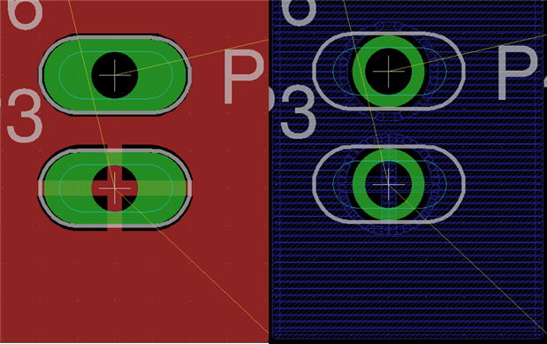
I am trying to make a custom through hole pad for a part but it needs to be either oblong or rectangular but there does not seem to be a way to specify anything but a circle drill hole. I know board houses can make plated through hole square pads but I cannot seem to figure out how to do it with Eagle CAD? I see I can draw tracks on the pad with a circle hole in it and block out part of the hole but I am not sure if that will be understood by the board house with respect to a rectangular plated through hole pad? Any suggestions?

  • Sign in to reply
  • Cancel

Top Replies

  • eugeny
    eugeny over 10 years ago in reply to Former Member +1
    Chris, what I learned about EAGLE that it can undo manual actions very well, but can not undo script actions. Thus before running the script backup your files, and if you do not like result of the script…
Parents
  • Former Member
    0 Former Member over 10 years ago

    After much searching, I finally reached out to Eagle CAD support and this is done by creating a normal pad and using a milling shape on the milling layer and creating a milling layer gerber file for the board house. I have attached an image of what a pad with this milling layer would look like assuming you are showing the milling layer. The only issue now is that the support team said I need to prevent traces from being underneath the milling shape for inner layers during auto routing. But I can only find a tRestrict or bRestrict layer which prevents traces from being routed during autoroute or vRestrict for via placement during autoroute. I have no idea what layer I can add to the part to prevent inner layer auto routing. the bKeepout and tKeepout are for part placement and again only pertain to the top and bottom layers. Any ideas?


    image

    • Cancel
    • Vote Up 0 Vote Down
    • Sign in to reply
    • Verify Answer
    • Cancel
  • autodeskguest
    0 autodeskguest over 10 years ago in reply to Former Member

    On 10/04/2015 5:49 a.m., chris spurrier wrote:

    After much searching, I finally reached out to Eagle CAD support and

    this is done by creating a normal pad and using a milling shape on the

    milling layer and creating a milling layer gerber file for the board

    house. I have attached an image of what a pad with this milling layer

    would look like assuming you are showing the milling layer. The only

    issue now is that the support team said I need to prevent traces from

    being underneath the milling shape for inner layers during auto routing.

    But I can only find a tRestrict or bRestrict layer which prevents traces

    from being routed during autoroute or vRestrict for via placement during

    autoroute. I have no idea what layer I can add to the part to prevent

    inner layer auto routing. the bKeepout and tKeepout are for part

    placement and again only pertain to the top and bottom layers. Any

    ideas?


    It should not be a worry if you are only milling slots in pads. Pads

    have pads on each of the inner the inner layers as well. These have the

    same signal name as the outer layer pads and so autorouting will not

    connect to them is the signal name is different. The size of the inner

    pads (restring) are set in the DRC settings.


    HTH

    Warren


    • Cancel
    • Vote Up 0 Vote Down
    • Sign in to reply
    • Verify Answer
    • Cancel
  • Former Member
    0 Former Member over 10 years ago in reply to autodeskguest

    That is what I thought too, but that only seems to apply to round pads (I did not check square pads). Check out the image attached. I have oblong pads with oblong milling. On the top (and bottom) layer the oblong pad is present, but the inner pads seem to be just round pads, not oblong pads. And from the image you can see the milling layer goes outside the round pad and theoretically a trace could end up being milled on the inner layers. I talked with Eagle CAD support again on this and they said it is a shortcoming of Eagle CAD and they are in the works on a fix or enhancement.


    In the image you can see the thin blue oblong shape, that is the milling layer. The red is the p layer and the blue is the first inner layer. You can see the pad on the inner layer is not the same as the pad on the top (or bottom) layer.

    image

    • Cancel
    • Vote Up 0 Vote Down
    • Sign in to reply
    • Verify Answer
    • Cancel
  • autodeskguest
    0 autodeskguest over 10 years ago in reply to Former Member

    On 4/10/2015 9:44 AM, chris spurrier wrote:

    That is what I thought too, but that only seems to apply to round pads

    (I did not check square pads). Check out the image attached. I have

    oblong pads with oblong milling. On the top (and bottom) layer the

    oblong pad is present, but the inner pads seem to be just round pads,

    not oblong pads. And from the image you can see the milling layer goes

    outside the round pad and theoretically a trace could end up being

    milled on the inner layers. I talked with Eagle CAD support again on

    this and they said it is a shortcoming of Eagle CAD and they are in the

    works on a fix or enhancement.


    In the image you can see the thin blue oblong shape, that is the milling

    layer. The red is the p layer and the blue is the first inner layer. You

    can see the pad on the inner layer is not the same as the pad on the top

    (or bottom) layer.


    Hi Chris,


    I emailed you privately on this, but I think its good to have it on the

    forum as well. Check the make-long-pad-inner-layer.ulp that comes with

    EAGLE. It basically makes sure the pad shape goes on all of the inner

    layers.


    In any case it an area for improvement in EAGLE.


    Best Regards,

    Jorge Garcia


    • Cancel
    • Vote Up 0 Vote Down
    • Sign in to reply
    • Reject Answer
    • Cancel
  • Former Member
    0 Former Member over 10 years ago in reply to autodeskguest

    Its funny you say that, I just got the exact same response from Eagle stating that is what I should use.


    Thanks for the response.


    By the way, do you have any idea how to reverse the actions of calling make-long-pad-inner-layer.ulp? I went from a 4-layer to 2-layer to see if it had an effect and now there are design rule issues. I am going to look at the ulp code to see if I can figure out how to reverse the steps it performs.


    Thanks again.


    P.S. - Well it look like it was you who got back to me image Thanks again. The only issue I have now is how to reverse the steps that were performed by the ulp script. I was able to undo the changes but I am thinking I will try to create an undo script since trying to manually delete the additional layers did not work.

    • Cancel
    • Vote Up 0 Vote Down
    • Sign in to reply
    • Verify Answer
    • Cancel
  • eugeny
    0 eugeny over 10 years ago in reply to Former Member

    Chris, what I learned about EAGLE that it can undo manual actions very well, but can not undo script actions. Thus before running the script backup your files, and if you do not like result of the script, close EAGLE without saving and reopen your project.

    • Cancel
    • Vote Up +1 Vote Down
    • Sign in to reply
    • Verify Answer
    • Cancel
Reply
  • eugeny
    0 eugeny over 10 years ago in reply to Former Member

    Chris, what I learned about EAGLE that it can undo manual actions very well, but can not undo script actions. Thus before running the script backup your files, and if you do not like result of the script, close EAGLE without saving and reopen your project.

    • Cancel
    • Vote Up +1 Vote Down
    • Sign in to reply
    • Verify Answer
    • Cancel
Children
No Data
element14 Community

element14 is the first online community specifically for engineers. Connect with your peers and get expert answers to your questions.

  • Members
  • Learn
  • Technologies
  • Challenges & Projects
  • Products
  • Store
  • About Us
  • Feedback & Support
  • FAQs
  • Terms of Use
  • Privacy Policy
  • Legal and Copyright Notices
  • Sitemap
  • Cookies

An Avnet Company © 2025 Premier Farnell Limited. All Rights Reserved.

Premier Farnell Ltd, registered in England and Wales (no 00876412), registered office: Farnell House, Forge Lane, Leeds LS12 2NE.

ICP 备案号 10220084.

Follow element14

  • X
  • Facebook
  • linkedin
  • YouTube