element14 Community
element14 Community
    Register Log In
  • Site
  • Search
  • Log In Register
  • Community Hub
    Community Hub
    • What's New on element14
    • Feedback and Support
    • Benefits of Membership
    • Personal Blogs
    • Members Area
    • Achievement Levels
  • Learn
    Learn
    • Ask an Expert
    • eBooks
    • element14 presents
    • Learning Center
    • Tech Spotlight
    • STEM Academy
    • Webinars, Training and Events
    • Learning Groups
  • Technologies
    Technologies
    • 3D Printing
    • FPGA
    • Industrial Automation
    • Internet of Things
    • Power & Energy
    • Sensors
    • Technology Groups
  • Challenges & Projects
    Challenges & Projects
    • Design Challenges
    • element14 presents Projects
    • Project14
    • Arduino Projects
    • Raspberry Pi Projects
    • Project Groups
  • Products
    Products
    • Arduino
    • Avnet & Tria Boards Community
    • Dev Tools
    • Manufacturers
    • Multicomp Pro
    • Product Groups
    • Raspberry Pi
    • RoadTests & Reviews
  • About Us
  • Store
    Store
    • Visit Your Store
    • Choose another store...
      • Europe
      •  Austria (German)
      •  Belgium (Dutch, French)
      •  Bulgaria (Bulgarian)
      •  Czech Republic (Czech)
      •  Denmark (Danish)
      •  Estonia (Estonian)
      •  Finland (Finnish)
      •  France (French)
      •  Germany (German)
      •  Hungary (Hungarian)
      •  Ireland
      •  Israel
      •  Italy (Italian)
      •  Latvia (Latvian)
      •  
      •  Lithuania (Lithuanian)
      •  Netherlands (Dutch)
      •  Norway (Norwegian)
      •  Poland (Polish)
      •  Portugal (Portuguese)
      •  Romania (Romanian)
      •  Russia (Russian)
      •  Slovakia (Slovak)
      •  Slovenia (Slovenian)
      •  Spain (Spanish)
      •  Sweden (Swedish)
      •  Switzerland(German, French)
      •  Turkey (Turkish)
      •  United Kingdom
      • Asia Pacific
      •  Australia
      •  China
      •  Hong Kong
      •  India
      • Japan
      •  Korea (Korean)
      •  Malaysia
      •  New Zealand
      •  Philippines
      •  Singapore
      •  Taiwan
      •  Thailand (Thai)
      • Vietnam
      • Americas
      •  Brazil (Portuguese)
      •  Canada
      •  Mexico (Spanish)
      •  United States
      Can't find the country/region you're looking for? Visit our export site or find a local distributor.
  • Translate
  • Profile
  • Settings
Autodesk EAGLE
  • Products
  • More
Autodesk EAGLE
EAGLE User Support (English) Creating custom parts used as placeholders
  • Blog
  • Forum
  • Documents
  • Events
  • Polls
  • Files
  • Members
  • Mentions
  • Sub-Groups
  • Tags
  • More
  • Cancel
  • New
Join Autodesk EAGLE to participate - click to join for free!
Actions
  • Share
  • More
  • Cancel
Forum Thread Details
  • State Not Answered
  • Replies 1 reply
  • Subscribers 178 subscribers
  • Views 563 views
  • Users 0 members are here
  • board
  • schematics
  • pcb
Related

Creating custom parts used as placeholders

nikola1010
nikola1010 over 10 years ago

Hi all,


I just started with Eagle and I am amazed how powerful this tool is.I would like to create custom pcb for my already existant parts like Arduino Nano, sensor boards and such.

Process would be consisted of adding custom stuff that I have in library and then just put on my new PBC board as components with pins and solder them to my newly created PCB.

I tried to learn from youtube videos how to use Eagle but one thing that I cannot find is explanation how to add pins holes for components like Arduino Nano or gsm sim800 module.

Those components already have pins on them and I just want to create fooprint that would place whole in propper way so I can solder components in that exact place.


Any help or hints would be much appreciated.

Thanks for helping out in advance.

Nikola.


EDIT:

PART #1

I've put my first part in this link http://privatepaste.com/download/b685973b40

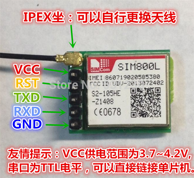
Goal was to make footprint for module in the picture.

Longer size is 21.80 mm and shorter size is 17.70 mm.

There are 5 pins that are to be used as connection on the board being developed.

I've put space between pins 2.54 mm (I've found those sizes on the net for breakaway headers).

Could someone please look at this part and tell me what I've done good/wrong and what should I change to make it as it should be.


PART #2

If I create new schematic and use this component, then create board and put it on it, what I need to add to make it possible to solder this

module on my new board?

Should putting it to my new board automatically use holes in this part and propagate them to my board?


PS: If anyone could make youtube on this matter it would be great!


sim800L on a pcb

  • Sign in to reply
  • Cancel
  • clem57
    0 clem57 over 10 years ago

    For part 2.i found the pads for a SIM800H which is similar to your SIM800L at Sim800H EAGLE library / footprint | dms Add your nets and posts and you should be complete.

    Clem

    • Cancel
    • Vote Up 0 Vote Down
    • Sign in to reply
    • Verify Answer
    • Cancel
element14 Community

element14 is the first online community specifically for engineers. Connect with your peers and get expert answers to your questions.

  • Members
  • Learn
  • Technologies
  • Challenges & Projects
  • Products
  • Store
  • About Us
  • Feedback & Support
  • FAQs
  • Terms of Use
  • Privacy Policy
  • Legal and Copyright Notices
  • Sitemap
  • Cookies

An Avnet Company © 2026 Premier Farnell Limited. All Rights Reserved.

Premier Farnell Ltd, registered in England and Wales (no 00876412), registered office: Farnell House, Forge Lane, Leeds LS12 2NE.

ICP 备案号 10220084.

Follow element14

  • X
  • Facebook
  • linkedin
  • YouTube