element14 Community
element14 Community
    Register Log In
  • Site
  • Search
  • Log In Register
  • Community Hub
    Community Hub
    • What's New on element14
    • Feedback and Support
    • Benefits of Membership
    • Personal Blogs
    • Members Area
    • Achievement Levels
  • Learn
    Learn
    • Ask an Expert
    • eBooks
    • element14 presents
    • Learning Center
    • Tech Spotlight
    • STEM Academy
    • Webinars, Training and Events
    • Learning Groups
  • Technologies
    Technologies
    • 3D Printing
    • FPGA
    • Industrial Automation
    • Internet of Things
    • Power & Energy
    • Sensors
    • Technology Groups
  • Challenges & Projects
    Challenges & Projects
    • Design Challenges
    • element14 presents Projects
    • Project14
    • Arduino Projects
    • Raspberry Pi Projects
    • Project Groups
  • Products
    Products
    • Arduino
    • Avnet & Tria Boards Community
    • Dev Tools
    • Manufacturers
    • Multicomp Pro
    • Product Groups
    • Raspberry Pi
    • RoadTests & Reviews
  • About Us
  • Store
    Store
    • Visit Your Store
    • Choose another store...
      • Europe
      •  Austria (German)
      •  Belgium (Dutch, French)
      •  Bulgaria (Bulgarian)
      •  Czech Republic (Czech)
      •  Denmark (Danish)
      •  Estonia (Estonian)
      •  Finland (Finnish)
      •  France (French)
      •  Germany (German)
      •  Hungary (Hungarian)
      •  Ireland
      •  Israel
      •  Italy (Italian)
      •  Latvia (Latvian)
      •  
      •  Lithuania (Lithuanian)
      •  Netherlands (Dutch)
      •  Norway (Norwegian)
      •  Poland (Polish)
      •  Portugal (Portuguese)
      •  Romania (Romanian)
      •  Russia (Russian)
      •  Slovakia (Slovak)
      •  Slovenia (Slovenian)
      •  Spain (Spanish)
      •  Sweden (Swedish)
      •  Switzerland(German, French)
      •  Turkey (Turkish)
      •  United Kingdom
      • Asia Pacific
      •  Australia
      •  China
      •  Hong Kong
      •  India
      • Japan
      •  Korea (Korean)
      •  Malaysia
      •  New Zealand
      •  Philippines
      •  Singapore
      •  Taiwan
      •  Thailand (Thai)
      • Vietnam
      • Americas
      •  Brazil (Portuguese)
      •  Canada
      •  Mexico (Spanish)
      •  United States
      Can't find the country/region you're looking for? Visit our export site or find a local distributor.
  • Translate
  • Profile
  • Settings
Autodesk EAGLE
  • Products
  • More
Autodesk EAGLE
EAGLE User Support (English) I've downloaded Arduino Pro Micro library but can't create board layout with added component (Eagle Lite)
  • Blog
  • Forum
  • Documents
  • Events
  • Polls
  • Files
  • Members
  • Mentions
  • Sub-Groups
  • Tags
  • More
  • Cancel
  • New
Join Autodesk EAGLE to participate - click to join for free!
Actions
  • Share
  • More
  • Cancel
Forum Thread Details
  • Replies 10 replies
  • Subscribers 179 subscribers
  • Views 1363 views
  • Users 0 members are here
Related

I've downloaded Arduino Pro Micro library but can't create board layout with added component (Eagle Lite)

Former Member
Former Member over 10 years ago

Hi All

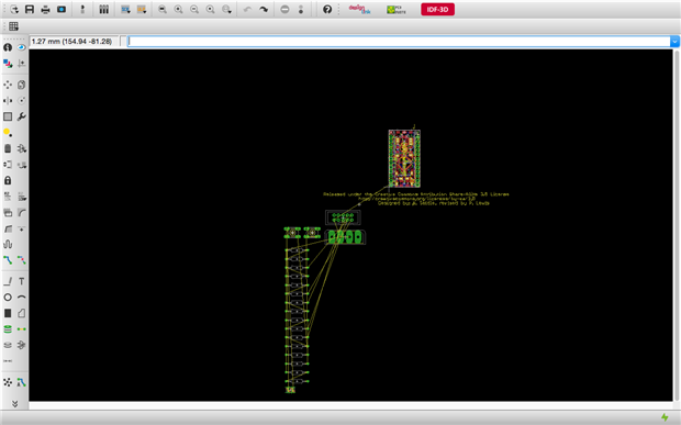
I'm having problems, moving components in Eagle lite. I've downloaded Element14 Arduino Pro Micro library and I've added my passive components to make a simple keyboard emulator. Now I'm trying to arrange the board layout I keep getting the following message:


The Light edition of EAGLE can't perform the requested action!


Some objects extend outside the allowed board area.


I know that the board limitation on Eagle lite are 100mm x 80mm, I can't see the board boundaries but I'm sure this would be a small board as the Aruino pro micro is only 30mm x 15mm.


My questions are,

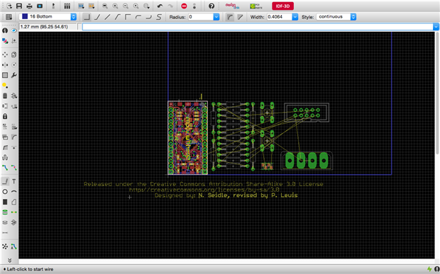
how do I view the board limitation boundaries?

can i add components outside the Element14 Aduino Pro Micro boundaries?


Thanks

Steve

  • Sign in to reply
  • Cancel
  • autodeskguest
    autodeskguest over 10 years ago

    Layer 20 (dimension) shows the outline of the board. The 100x80mm

    limitation starts at the origin (0,0). If your board is offset from the

    origin it's possible that you're outside of the limit.

    --

    Web access to CadSoft support forums at www.eaglecentral.ca.  Where the CadSoft EAGLE community meets.


    • Cancel
    • Vote Up 0 Vote Down
    • Sign in to reply
    • Cancel
  • autodeskguest
    autodeskguest over 10 years ago in reply to autodeskguest

    Thanks for the reply, just looking at layers and they start at layer 90

    and end at layer 254. How do I select layer 20?


    Thanks again, regards Steve


    --

    To view any images and attachments in this post, visit:

    http://www.element14.com/community/message/163732


    • Cancel
    • Vote Up 0 Vote Down
    • Sign in to reply
    • Cancel
  • Former Member
    Former Member over 10 years ago in reply to autodeskguest

    Hi, Thanks for the reply, I've found layer 20 and can now see the boundaries of the board area but the board area seems to be taken up by all of the Arduino Pro Micro layout, however the physical size of the Pro Micro is only 30mm x 15mm. I'm puzzled to why such a small board seams to take up all the 100mm x 80mm dimensions. I downloaded the Arduino Pro Micro library from Element14.


    Any ideas, why I'm not seeing the Arduino as a smaller component within the 100mm x 80mm build area?


    Regards Steve

    • Cancel
    • Vote Up 0 Vote Down
    • Sign in to reply
    • Cancel
  • autodeskguest
    autodeskguest over 10 years ago in reply to Former Member

    On 19/10/15 18:02, steven robinson wrote:

    Hi, Thanks for the reply, I've found layer 20 and can now see the

    boundaries of the board area but the board area seems to be taken up by

    all of the Arduino Pro Micro layout, however the physical size of the

    Pro Micro is only 30mm x 15mm. I'm puzzled to why such a small board

    seams to take up all the 100mm x 80mm dimensions. I downloaded the

    Arduino Pro Micro library from Element14.


    Any ideas, why I'm not seeing the Arduino as a smaller component within

    the 100mm x 80mm build area?


    Post a screenshot or two, it'll make it a lot easier to see what you're

    referring to.


    • Cancel
    • Vote Up 0 Vote Down
    • Sign in to reply
    • Cancel
  • Former Member
    Former Member over 10 years ago in reply to autodeskguest

    Screen shot below, the frame for the board limits seem to be from the bottom left of the Arduino board but I can't get the outline of the limits of the board (100mm x 80mm) to display. I've realised I can move my components to the right of the Arduino so I'm guessing the board limits are working just not showing. My other problem is I don't seem to be able to rotate the group of components making up the arduino board. Any ideas?


    Thanks for your help

    image

    • Cancel
    • Vote Up 0 Vote Down
    • Sign in to reply
    • Cancel
  • Former Member
    Former Member over 10 years ago in reply to autodeskguest

    Think I'm getting there image I used the wire tool to draw a rectangular limit to the board size max of Eagle Lite the place my compost accordingly, I still can't rotate the arduino component though so any guidance would be appreciated.


    Thanks in advance


    image

    • Cancel
    • Vote Up 0 Vote Down
    • Sign in to reply
    • Cancel
  • autodeskguest
    autodeskguest over 10 years ago in reply to Former Member

    On 19/10/15 22:38, steven robinson wrote:

    Think I'm getting there image I used the wire tool to draw a rectangular

    limit to the board size max of Eagle Lite the place my compost

    accordingly, I still can't rotate the arduino component though so any

    guidance would be appreciated.


    Well, first, there should normally be an outline of the allowed area in

    layer 20 when you first create a board. Eagle does this specifically to

    help with what you're currently going through. However, you've got past

    that now, so...


    You won't be able to rotate the arduino in situ if its bottom left

    corner is at the origin. To do so would put some of the pins outside the

    valid area to the left. Instead, you should MOVE it. Drag it away into

    the free space above and to the right, then right-click to rotate it

    while moving. Now place it somewhere completely within your blue box and

    it should work.


    • Cancel
    • Vote Up 0 Vote Down
    • Sign in to reply
    • Cancel
  • Former Member
    Former Member over 10 years ago in reply to autodeskguest

    Any ideas, how I get the outline of the permited board area to display? I've also got problems with one air wire, I've tracked it down to none terminated pins on a couple on connectors, how do I terminate these pins, i.e. let the eagle know they have no purpose in the circuit ?


    thanks in advance

    Steve

    • Cancel
    • Vote Up 0 Vote Down
    • Sign in to reply
    • Cancel
  • autodeskguest
    autodeskguest over 10 years ago in reply to Former Member

    On 25/10/15 01:25, steven robinson wrote:

    Any ideas, how I get the outline of the permited board area to display?


    There's nothing magic about the outline, it's just a line drawn in the

    Dimension layer. Eagle puts it there when you create a new board, but

    after that it's just a line.


    I've also got problems with one air wire, I've tracked it down to none

    terminated pins on a couple on connectors, how do I terminate these

    pins, i.e. let the eagle know they have no purpose in the circuit ?


    You don't need to. Well, you might, in some cases, need something on a

    pin to avoid an ERC warning or error, but not for a connector pin. In

    fact the only cases that should produce errors are ones where your

    circuit probably needs something connected there. Any others are library

    bugs.


    What problem are you having with this airwire? Have you tried RATSNEST

    to re-calculate? If it doesn't correspond to an active, unrouted net,

    that should remove it.


    • Cancel
    • Vote Up 0 Vote Down
    • Sign in to reply
    • Cancel
  • Former Member
    Former Member over 10 years ago in reply to autodeskguest

    I've had one air wire for ages, I found an un routed net and corrected it, re did autorouter and RATSNEST but it didn't resolve the problem so I deliberately added an un routed net to check RATSNEST was working. As I thought it would, it now reported two air wires. I un did the deliberate un routed net and now I have two air wires. Both I now suspect are not there but eagle is not refreshing. Any ideas ho I can  resolve the air wires issue. I now suspect both air wire are not present.


    thanks

    Steve

    • Cancel
    • Vote Up 0 Vote Down
    • Sign in to reply
    • Cancel
element14 Community

element14 is the first online community specifically for engineers. Connect with your peers and get expert answers to your questions.

  • Members
  • Learn
  • Technologies
  • Challenges & Projects
  • Products
  • Store
  • About Us
  • Feedback & Support
  • FAQs
  • Terms of Use
  • Privacy Policy
  • Legal and Copyright Notices
  • Sitemap
  • Cookies

An Avnet Company © 2025 Premier Farnell Limited. All Rights Reserved.

Premier Farnell Ltd, registered in England and Wales (no 00876412), registered office: Farnell House, Forge Lane, Leeds LS12 2NE.

ICP 备案号 10220084.

Follow element14

  • X
  • Facebook
  • linkedin
  • YouTube