element14 Community
element14 Community
    Register Log In
  • Site
  • Search
  • Log In Register
  • Community Hub
    Community Hub
    • What's New on element14
    • Feedback and Support
    • Benefits of Membership
    • Personal Blogs
    • Members Area
    • Achievement Levels
  • Learn
    Learn
    • Ask an Expert
    • eBooks
    • element14 presents
    • Learning Center
    • Tech Spotlight
    • STEM Academy
    • Webinars, Training and Events
    • Learning Groups
  • Technologies
    Technologies
    • 3D Printing
    • FPGA
    • Industrial Automation
    • Internet of Things
    • Power & Energy
    • Sensors
    • Technology Groups
  • Challenges & Projects
    Challenges & Projects
    • Design Challenges
    • element14 presents Projects
    • Project14
    • Arduino Projects
    • Raspberry Pi Projects
    • Project Groups
  • Products
    Products
    • Arduino
    • Avnet & Tria Boards Community
    • Dev Tools
    • Manufacturers
    • Multicomp Pro
    • Product Groups
    • Raspberry Pi
    • RoadTests & Reviews
  • About Us
    About the element14 Community
  • Store
    Store
    • Visit Your Store
    • Choose another store...
      • Europe
      •  Austria (German)
      •  Belgium (Dutch, French)
      •  Bulgaria (Bulgarian)
      •  Czech Republic (Czech)
      •  Denmark (Danish)
      •  Estonia (Estonian)
      •  Finland (Finnish)
      •  France (French)
      •  Germany (German)
      •  Hungary (Hungarian)
      •  Ireland
      •  Israel
      •  Italy (Italian)
      •  Latvia (Latvian)
      •  
      •  Lithuania (Lithuanian)
      •  Netherlands (Dutch)
      •  Norway (Norwegian)
      •  Poland (Polish)
      •  Portugal (Portuguese)
      •  Romania (Romanian)
      •  Russia (Russian)
      •  Slovakia (Slovak)
      •  Slovenia (Slovenian)
      •  Spain (Spanish)
      •  Sweden (Swedish)
      •  Switzerland(German, French)
      •  Turkey (Turkish)
      •  United Kingdom
      • Asia Pacific
      •  Australia
      •  China
      •  Hong Kong
      •  India
      •  Japan
      •  Korea (Korean)
      •  Malaysia
      •  New Zealand
      •  Philippines
      •  Singapore
      •  Taiwan
      •  Thailand (Thai)
      •  Vietnam
      • Americas
      •  Brazil (Portuguese)
      •  Canada
      •  Mexico (Spanish)
      •  United States
      Can't find the country/region you're looking for? Visit our export site or find a local distributor.
  • Translate
  • Profile
  • Settings
Autodesk EAGLE
  • Products
  • More
Autodesk EAGLE
Forum Amega328p-au shorted pins ?
  • Blog
  • Forum
  • Documents
  • Events
  • Polls
  • Files
  • Members
  • Mentions
  • Sub-Groups
  • Tags
  • More
  • Cancel
  • New
Join Autodesk EAGLE to participate - click to join for free!
Actions
  • Share
  • More
  • Cancel
Forum Thread Details
  • State Suggested Answer
  • Replies 47 replies
  • Answers 6 answers
  • Subscribers 191 subscribers
  • Views 7233 views
  • Users 0 members are here
Related

Amega328p-au shorted pins ?

n2nxz
n2nxz over 9 years ago

Finally motivated myself into trying Eagle files only to see my original instincts told me NOT to bother.

The last thing I expected was not finding common components in the library.My first mistake to assume that an Atmega328p-au would be one of the easiest to find.Not so and had to search the ends of the earth to find it and manually place it into the LIBR directory.After a 4 hour search and finally having this IC in my schematic layout I now see"shorts on several pins of this chip in the BRD window.The worse possible places no less on 3.3v and ground

I can probably modify this file but now getting far deeper into a simple project I thought would be straight forward.

Is it a software glitch causing this or a bad library file ?

Anyone know where to find a working Atmega328p-au footprint

See attached screen shot of the issue.

image

  • Sign in to reply
  • Cancel
Parents
  • rachaelp
    0 rachaelp over 9 years ago

    Hi James,


    James Zelazny jr wrote:


    Finally motivated myself into trying Eagle files only to see my original instincts told me NOT to bother.


    I get it you are feeling frustrated, the first time I tried to use EAGLE it didn't go so well. I had to sit down and read the manual and tutorials to understand how it works as previously I had spent a lot of time with DxDesigner/PADS and OrCAD, and EAGLE was quite a change from both of these.


    James Zelazny jr wrote:


    The last thing I expected was not finding common components in the library.My first mistake to assume that an Atmega328p-au would be one of the easiest to find.Not so and had to search the ends of the earth to find it and manually place it into the LIBR directory.After a 4 hour search and finally having this IC in my schematic layout


    So the issue here is assuming the bundled parts library is useful. As with the "free" parts libraries that are bundled with absolutely all ECAD packages, not just EAGLE, you get what you pay for. If you value your time and the integrity of your designs you'll just create your own libraries. It's actually quite easy once you've done a few parts. There are great tutorials to get you started on Adafruit and Dangerous Prototypes. To start this from scratch and do it properly yourself would have been a fraction of the time you spent searching.


    James Zelazny jr wrote:


    .After a 4 hour search and finally having this IC in my schematic layout I now see "shorts" on several pins of this chip in the BRD window.The worse possible places no less on 3.3v and ground !!

    I can probably modify this file but now getting far deeper into a simple project I thought would be straight forward.

    Is it a software glitch causing this or a bad library file ?

    Anyone know where to find a working Atmega328p-au footprint

    See attached screen shot of the issue.

    image

    It looks like it's just showing air wires between pins on the same net, not between nets i.e. it's connecting all the GND and separately all the 3.3V but I am a little perplexed why as it doesn't look like you have any nets added on the schematic and dropping in a part with multiple pads on the same pin of the part doesn't show air wires for me until I connect up a net in the schematic. Could you put the lib/sch/brd files up on here so we can take a look at what you have done please?


    Best Regards,


    Rachael

    • Cancel
    • Vote Up 0 Vote Down
    • Sign in to reply
    • Verify Answer
    • Cancel
  • n2nxz
    0 n2nxz over 9 years ago in reply to rachaelp

    The screenshot is just me adding the very first component into the work space.I did nothing but add the library file for the Atmega328p-au,started the program and was the very first component selected.I did nothing but check the board view to find these pins already wired.

    I spent an entire day downloading as many components for my project as possible and had it just about completed on the second day when I discovered many wires in places that should not have been.So,cleaned the slate and even re-installed Eagle and started over.

    This time I wanted to place a component and do little at a time while checking for bogus traces.That is when I finally discovered these connections right off before even starting the project...just merely adding the component and this shows up.

    I also would like to note that sometimes the program crashes and will lose my work unless I save each and everything I do.

    Frustrated is a mild term at this point.

    So basically,I open the program,create a project and the first thing I do is select the Atmega328p-au and put it into the schematic work space.and that is what I am getting.I have done nothing else

    Here is the file I used and wonder if it is just a bad file itself ?

    https://www.snapeda.com/parts/ATMEGA328P-AU/Atmel/view-part/

    Give it a try and see what you get ?

    • Cancel
    • Vote Up 0 Vote Down
    • Sign in to reply
    • Verify Answer
    • Cancel
  • rachaelp
    0 rachaelp over 9 years ago in reply to n2nxz

    Hi James,


    I've downloaded it and what it is doing isn't wrong as such. The VCC and GND pins on that part have their pin type set to PWR. When you place them on the board they try and connect up to identically named power nets from other devices with pins of type PWR. As soon as you connect them up to what you want them to connect to then if they are different they will no longer connect to the other devices. Does that make sense?


    I tend to not use the PWR pin type in my devices (although I was experimenting with it recently to make a ULP simpler, I will go for the hard approach now I have seen this but that's a different story) so I haven't had this happen before. It's not a problem as log as you fully connect everything up how you want in the schematic and don't end up with connections you didn't intend because it used device PWR pin names to guess at connections.


    Best Regards,


    Rachael

    • Cancel
    • Vote Up 0 Vote Down
    • Sign in to reply
    • Verify Answer
    • Cancel
  • rachaelp
    0 rachaelp over 9 years ago in reply to n2nxz

    Hi James,


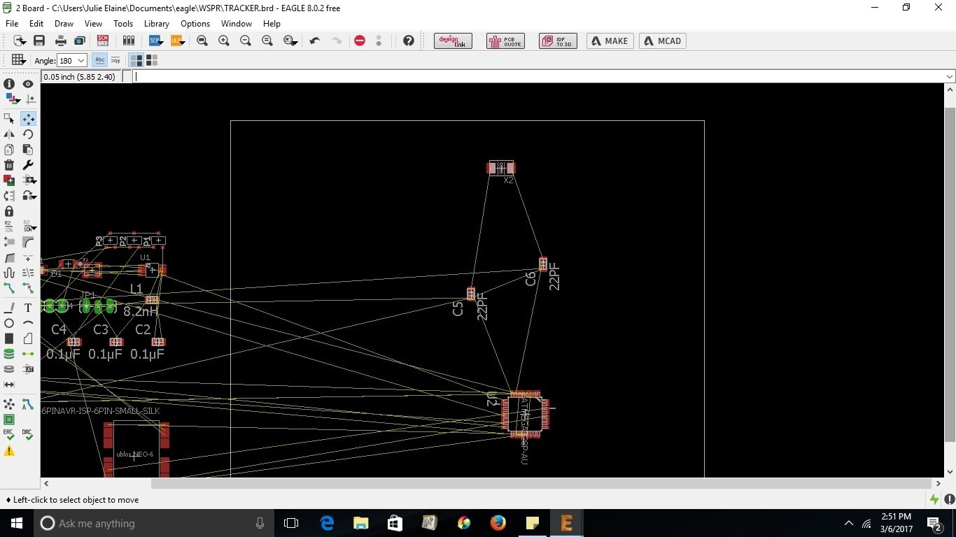
    I think it's probably ok. If you place the crystal where you want it, near the IC pins and then the caps the other side where you want them, if you then press the ratsnest button or type RAT <return> you should see it re-optimise the air wires to the order you expect.


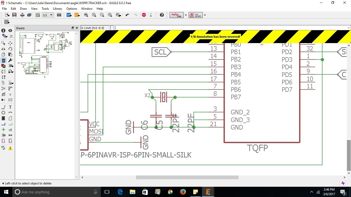
    The other thing to note is in the image of the schematic above it is warning about forward and back annotation being severed. You need to make sure you always have both the schematic and board open and never make any changes that will affect the netlist when one or the other is closed otherwise you will end up in a mess.


    Best Regards,


    Rachael

    • Cancel
    • Vote Up 0 Vote Down
    • Sign in to reply
    • Verify Answer
    • Cancel
  • n2nxz
    0 n2nxz over 9 years ago in reply to n2nxz

    Maybe it is correct and I am not used to organizing things properly on board view?

    • Cancel
    • Vote Up 0 Vote Down
    • Sign in to reply
    • Verify Answer
    • Cancel
  • n2nxz
    0 n2nxz over 9 years ago in reply to n2nxz

    Here is my schematic and board view.

    Seems the crystal pins should be connected to the IC and the caps after that to ground the way it was drawn ?

    image

    image

    • Cancel
    • Vote Up 0 Vote Down
    • Sign in to reply
    • Verify Answer
    • Cancel
  • n2nxz
    0 n2nxz over 9 years ago in reply to n2nxz

    Thought to share the work done already on my schematic but pretty sure there are errors somewhere along the line.

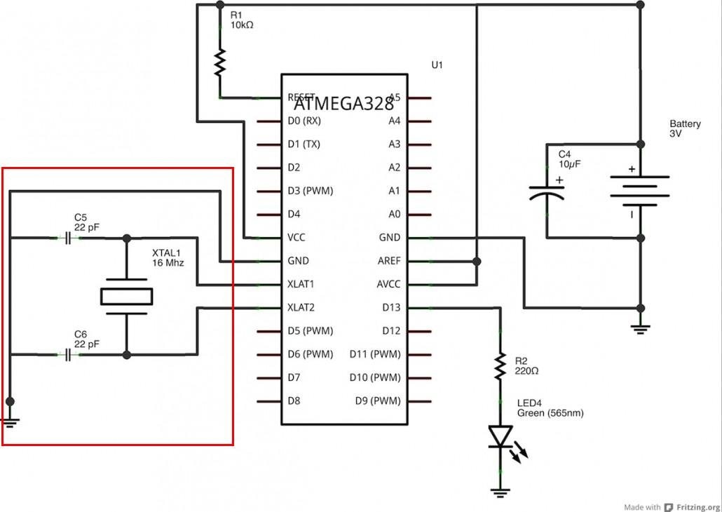
    The biggest hurdle so far is getting a crystal connected to an IC.

    Not really sure why it does not show up properly in board view but here is my goal.

    See drawing -

    When I try this the caps end up on the IC pins and the crystal on the opposite side.I do not think the circuit will function properly this way.

    I am making connections exactly as the diagram shows.Missing a step somewhere ?

    image

    • Cancel
    • Vote Up 0 Vote Down
    • Sign in to reply
    • Verify Answer
    • Cancel
  • n2nxz
    0 n2nxz over 9 years ago in reply to rachaelp

    Rachael,

    Thank you for your patience.

    So far have made up some of my schematic.I`ll do a bit here and there and check over the work as I go.

    Still some things to learn but feel pretty good about the way it works so far.No crashes yet and the latest version is far better to use with noticeable changes from previous versions tried.My circuit is very basic compared to most out there so should go fairly well.Even if it doesn't,at least this time have a chance image

    I`ll probably be back with some questions eventually and hope help will be available.

    Jim

    • Cancel
    • Vote Up +1 Vote Down
    • Sign in to reply
    • Verify Answer
    • Cancel
  • rachaelp
    0 rachaelp over 9 years ago in reply to n2nxz

    Hi James,


    Thanks for the updates. If you continue to use EAGLE on your newer laptop, there's plenty of people here to help out if you have any further questions.


    Good luck with you project!


    Best Regards,


    Rachael

    • Cancel
    • Vote Up 0 Vote Down
    • Sign in to reply
    • Verify Answer
    • Cancel
  • n2nxz
    0 n2nxz over 9 years ago in reply to n2nxz

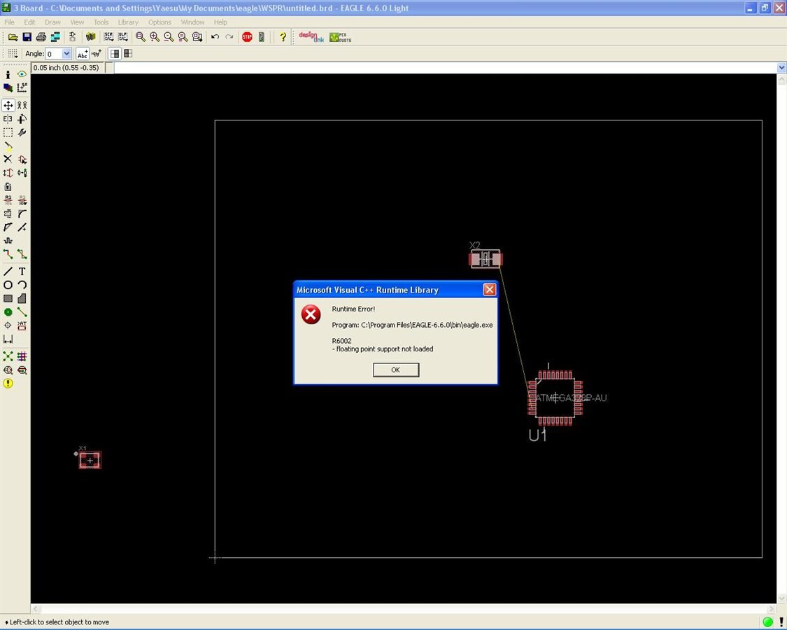
    All my problems are because of Windows XP C++ library issues and always no solution.Been down this road 100`s of times and this happens with some programs and not others.Not going to waste my life on fixing it.

    However,installed the latest version of Eagle onto a newer laptop here,transferred my new LBR files and first shot everything works like it should.

    Going to get to work,enough time wasted already.

    Thanks for those who tried to help and maybe this posting will help someone in the future rather than wasting time.

    Jim

    • Cancel
    • Vote Up +1 Vote Down
    • Sign in to reply
    • Verify Answer
    • Reject Answer
    • Cancel
  • n2nxz
    0 n2nxz over 9 years ago in reply to n2nxz

    Since I hate to go down without a fight,here is an example of what is happening when I try simple things using Eagle.

    Is it something I am doing wrong or is this an issue with software on my machine?

    The version of Eagle I dug up from backup CD`s since V8 and V7 was not working.It appeared this older version was working much better but after making this video,it crashed while sitting in board view so now I have 2 issues again.

    Here is a short video of what I am trying to accomplish starting with 3 components and a simple crystal connection.

    https://youtu.be/oZavqxPt9U0

    Ignore the sound,that was a ham radio tied into my sound card by mistake.

    Also,this error popped up while processing this video and has been doing this on both working versions of Eagle.

    But you can still see a missing connection on that crystal.

    I may just be SOL with this project and will try a newer machine today and see how that goes.

    Jim

    image

    • Cancel
    • Vote Up 0 Vote Down
    • Sign in to reply
    • Verify Answer
    • Cancel
  • n2nxz
    0 n2nxz over 9 years ago in reply to n2nxz

    Just to get an idea how NOT concerned I am with cosmetics but rather function here is previous builds.

    My goal now is to reduce weight and wanted to go with surface mounted components.In reality,swapping out an Atmega328-pu with a 328p-au is a small reduction in weight.Adding the PCB pretty much replaces the weight I saved.so trying to be smart not pretty

    https://www.qrp-labs.com/flights/u3s7

    • Cancel
    • Vote Up 0 Vote Down
    • Sign in to reply
    • Verify Answer
    • Cancel
  • rachaelp
    0 rachaelp over 9 years ago in reply to n2nxz

    James Zelazny jr wrote:


    I even think I can reduce the weight over PCB materials which was the goal anyhow.


    You can specify thinner than standard PCB's and they would be really light. Look at all the options on Eurocircuits as an example. You end up paying quite a bit more for non standard builds though.


    Best Regards,


    Rachael

    • Cancel
    • Vote Up 0 Vote Down
    • Sign in to reply
    • Verify Answer
    • Cancel
Reply
  • rachaelp
    0 rachaelp over 9 years ago in reply to n2nxz

    James Zelazny jr wrote:


    I even think I can reduce the weight over PCB materials which was the goal anyhow.


    You can specify thinner than standard PCB's and they would be really light. Look at all the options on Eurocircuits as an example. You end up paying quite a bit more for non standard builds though.


    Best Regards,


    Rachael

    • Cancel
    • Vote Up 0 Vote Down
    • Sign in to reply
    • Verify Answer
    • Cancel
Children
No Data
element14 Community

element14 is the first online community specifically for engineers. Connect with your peers and get expert answers to your questions.

  • Members
  • Learn
  • Technologies
  • Challenges & Projects
  • Products
  • Store
  • About Us
  • Feedback & Support
  • FAQs
  • Terms of Use
  • Privacy Policy
  • Legal and Copyright Notices
  • Sitemap
  • Cookies

An Avnet Company © 2026 Premier Farnell Limited. All Rights Reserved.

Premier Farnell Ltd, registered in England and Wales (no 00876412), registered office: Farnell House, Forge Lane, Leeds LS12 2NE.

Follow element14

  • X
  • Facebook
  • linkedin
  • YouTube