element14 Community
element14 Community
    Register Log In
  • Site
  • Search
  • Log In Register
  • Community Hub
    Community Hub
    • What's New on element14
    • Feedback and Support
    • Benefits of Membership
    • Personal Blogs
    • Members Area
    • Achievement Levels
  • Learn
    Learn
    • Ask an Expert
    • eBooks
    • element14 presents
    • Learning Center
    • Tech Spotlight
    • STEM Academy
    • Webinars, Training and Events
    • Learning Groups
  • Technologies
    Technologies
    • 3D Printing
    • FPGA
    • Industrial Automation
    • Internet of Things
    • Power & Energy
    • Sensors
    • Technology Groups
  • Challenges & Projects
    Challenges & Projects
    • Design Challenges
    • element14 presents Projects
    • Project14
    • Arduino Projects
    • Raspberry Pi Projects
    • Project Groups
  • Products
    Products
    • Arduino
    • Avnet & Tria Boards Community
    • Dev Tools
    • Manufacturers
    • Multicomp Pro
    • Product Groups
    • Raspberry Pi
    • RoadTests & Reviews
  • About Us
    About the element14 Community
  • Store
    Store
    • Visit Your Store
    • Choose another store...
      • Europe
      •  Austria (German)
      •  Belgium (Dutch, French)
      •  Bulgaria (Bulgarian)
      •  Czech Republic (Czech)
      •  Denmark (Danish)
      •  Estonia (Estonian)
      •  Finland (Finnish)
      •  France (French)
      •  Germany (German)
      •  Hungary (Hungarian)
      •  Ireland
      •  Israel
      •  Italy (Italian)
      •  Latvia (Latvian)
      •  
      •  Lithuania (Lithuanian)
      •  Netherlands (Dutch)
      •  Norway (Norwegian)
      •  Poland (Polish)
      •  Portugal (Portuguese)
      •  Romania (Romanian)
      •  Russia (Russian)
      •  Slovakia (Slovak)
      •  Slovenia (Slovenian)
      •  Spain (Spanish)
      •  Sweden (Swedish)
      •  Switzerland(German, French)
      •  Turkey (Turkish)
      •  United Kingdom
      • Asia Pacific
      •  Australia
      •  China
      •  Hong Kong
      •  India
      •  Japan
      •  Korea (Korean)
      •  Malaysia
      •  New Zealand
      •  Philippines
      •  Singapore
      •  Taiwan
      •  Thailand (Thai)
      •  Vietnam
      • Americas
      •  Brazil (Portuguese)
      •  Canada
      •  Mexico (Spanish)
      •  United States
      Can't find the country/region you're looking for? Visit our export site or find a local distributor.
  • Translate
  • Profile
  • Settings
Autodesk EAGLE
  • Products
  • More
Autodesk EAGLE
Forum Colorsound Power boost noise issue
  • Blog
  • Forum
  • Documents
  • Events
  • Polls
  • Files
  • Members
  • Mentions
  • Sub-Groups
  • Tags
  • More
  • Cancel
  • New
Join Autodesk EAGLE to participate - click to join for free!
Actions
  • Share
  • More
  • Cancel
Forum Thread Details
  • State Verified Answer
  • Replies 132 replies
  • Answers 52 answers
  • Subscribers 191 subscribers
  • Views 22080 views
  • Users 0 members are here
  • colorsound power boost issue
Related

Colorsound Power boost noise issue

Andy Betts
Andy Betts over 9 years ago

A while ago I posted regarding transistors etc for a Colorsound Power boost clone pedal I was working on. Well, after many months I've actually finished 2 of them... They are identical to an original right down to the size of the PCB.and the components used. There is one slight difference in so far as the first board was a direct print from an Eagle layout, the second board was a 121 trace of an original PCB, only slightly different from the eagle board.


This is the Eagle board

image

This is board 2, a 121 copy of an original Colorsound Power boost PCB, and also a photo of an original

imageimage


The component side is like this.. mine is on the left, the genuine PCB is on the right. The pots on my board are mounted to the board like the original... Just from the other side. The reason for this is purely down to the thread length on the pots. The thread on my pots isn't long enough to go through the PCB, and then through the enclosure as well.


20264850_10155652356109783_7777668817152516572_n.jpg?oh=d17440c16b7064d06164d2a2c9783dba&oe=59EEEC46  image


The schematic used was this one..... a simple circuit which is basically a pre-amp that boosts the volume and treble and bass.


image


The components on the first board were all brand new, where the components on the 2nd board were mostly NOS for a visual vintage vibe.


I have an issue on both boards that I'm trying to troubleshoot, and currently i have reached out to 2 DIY effect pedal forums with no real resolution. i'm hoping someone here may be able to point me in the right direction, i'll try to give as much information as possible.


I have a cycled ticking noise that increases in volume when you turn the volume up on the pedal. it's not affected by the guitar volume, and stays there even when you turn the guitar down. Check out this video.


This video is unavailable.
You don't have permission to edit metadata of this video.


This video is unavailable.
You don't have permission to edit metadata of this video.


This video is unavailable.
You don't have permission to edit metadata of this video.


The last video shows a slight earth problem that may or may not have anything to do with the noise. i thought i'd include it anyway.


I have taken voltage readings off my pedal, and compared them to the readings from a genuine pedal (I'll say at this stage that my pedal is exactly the same as the genuine pedal as regards component values)


Genuine Pedal voltages

Battery: 18.84V

Q1 C 6.43V B 3.92V E 3.54V

Q2 C 11.53V B 6.44V E 5.82V

Q3 C 10.19V B 2.77V E 2.23V


My voltages:

Battery: 18.80V

Q1 C 6.37V B 3.90V E 3.52V

Q2 C 11.36V B 6.37V E 5.74V

Q3 C 10.54V B 2.75V E 2.19V

  • Sign in to reply
  • Cancel
Parents
  • jw0752
    0 jw0752 over 9 years ago

    Hi Andy and Others,


    In a new experiment tonight I wanted to see how low the input to the two transistor amplifier had to be so that the output would not clip at full volume. This turned out to be at the limits of my test equipment so my results were not very precise.


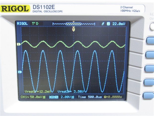
    image


    Here we have an input of 1 kHz at 12.2 mV rms and the gain control is at max. This produces an output with no load of 3.56 V rms and an approximate gain of 300.


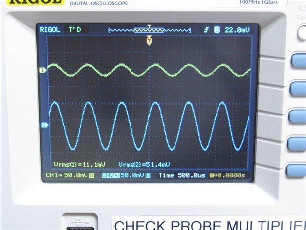
    image


    In this photo we have set the gain control to minimum. While I have not changed the input from the signal generator we see that the scope is now calculating the input voltage to be 11.1 mV rms. The output with no load is now 51.4 mV rms for a gain of approximately 5. Any setting of the gain control or increase in the input that pushes the output beyond 3.6 V rms shows clipping on the output.


    John

    • Cancel
    • Vote Up +5 Vote Down
    • Sign in to reply
    • Verify Answer
    • Cancel
  • jc2048
    0 jc2048 over 9 years ago in reply to jw0752

    This turned out to be at the limits of my test equipment so my results were not very precise.

    You are allowed to put an attenuator at the input if you want to. The input resistance of the preamp is around 150k, so it would hardly load a simple potential divider if you keep the values low. Measure what goes into the attenuator and divide by the attenuation.


    Alternatively, have a look and see what your test meters can manage measuring AC.

    • Cancel
    • Vote Up +1 Vote Down
    • Sign in to reply
    • Verify Answer
    • Reject Answer
    • Cancel
  • jw0752
    0 jw0752 over 9 years ago in reply to jc2048

    Hi Jon,

    By this morning my mind had finally realized that I wasn't at the limit as I still could switch the oscilloscope to RX1 and then I read your excellent suggestion to use an attenuator on my signal generator. I retract my statement and tonight I will recheck my readings.

    John

    • Cancel
    • Vote Up 0 Vote Down
    • Sign in to reply
    • Verify Answer
    • Cancel
  • Andy Betts
    0 Andy Betts over 9 years ago in reply to jc2048

    I'll do that tonight Jon.... At work now. I know for sure I don't have 100uf to hand, so i'll likely have to daisy chain a few together to make the value up.

    • Cancel
    • Vote Up 0 Vote Down
    • Sign in to reply
    • Verify Answer
    • Cancel
  • jc2048
    0 jc2048 over 9 years ago in reply to Andy Betts

    As an experiment, can you now try increasing the size of the capacitor that goes from the emitter of Q2 to ground (currently 22uF). Let's overdo it a bit and go to 100uF if you've got one to hand - if not, parallel some smaller values. Does that stop the oscillation?

    • Cancel
    • Vote Up 0 Vote Down
    • Sign in to reply
    • Verify Answer
    • Cancel
  • dougw
    0 dougw over 9 years ago in reply to Andy Betts

    If you don't like the idea of using a negative feedback capacitor to kill the oscillation, you could investigate the pot. Maybe the pot has parasitic capacitance that is adding unwanted gain. (and touching it will alter this parasitic capacitance). You could try substituting a resistor for the pot to see if this is the problem.

    • Cancel
    • Vote Up +1 Vote Down
    • Sign in to reply
    • Verify Answer
    • Cancel
  • jw0752
    0 jw0752 over 9 years ago in reply to Andy Betts

    These tests seem to confirm that the noise is coming from the 2 transistor amplifier. I was a little surprised that your touching the volume control had the effect that it did. The shaft of the control should be isolated from the input and grounded through the mounting screw of the control. I have to think about all of this some more. Perhaps some of this will make more sense to Jon, Michael or Shabaz than it make to me.


    John

    • Cancel
    • Vote Up 0 Vote Down
    • Sign in to reply
    • Verify Answer
    • Cancel
  • Andy Betts
    0 Andy Betts over 9 years ago in reply to Andy Betts

    While i have it disconnected from the tone section and the output section, now is an opportune time to get some scope readings probably of just the pre-amp section seeing as it looks like that's where it's originating from.

    • Cancel
    • Vote Up +1 Vote Down
    • Sign in to reply
    • Verify Answer
    • Reject Answer
    • Cancel
  • Andy Betts
    0 Andy Betts over 9 years ago in reply to jw0752

    John,


    yes. it does..... I tried it without the guitar plugged in, and also with the shorting plug and it still motor boats. Without the guitar plugged in it is quieter, but it is still there.


    Check out the short video


    This video is unavailable.
    You don't have permission to edit metadata of this video.

    • Cancel
    • Vote Up +1 Vote Down
    • Sign in to reply
    • Verify Answer
    • Reject Answer
    • Cancel
  • jw0752
    0 jw0752 over 9 years ago in reply to Andy Betts

    Hi Andy,


    Does it motor boat when the guitar isn't plugged in?


    John

    • Cancel
    • Vote Up 0 Vote Down
    • Sign in to reply
    • Verify Answer
    • Cancel
  • Andy Betts
    0 Andy Betts over 9 years ago in reply to Andy Betts

    Ok chaps, Now I've lifted the correct capacitor (thanks John image ), I've tried the test again.... And the motor boating is still there, which at least tells us that it's root cause is in the pre-amp section


    This video is unavailable.
    You don't have permission to edit metadata of this video.

    • Cancel
    • Vote Up +1 Vote Down
    • Sign in to reply
    • Verify Answer
    • Reject Answer
    • Cancel
  • Andy Betts
    0 Andy Betts over 9 years ago in reply to jw0752

    Ooops! I'll try again


    Thanks John

    • Cancel
    • Vote Up 0 Vote Down
    • Sign in to reply
    • Verify Answer
    • Cancel
  • jw0752
    0 jw0752 over 9 years ago in reply to Andy Betts

    Hi Andy,

    I think you got the wrong capacitor. If my reading is correct it should have been the small 4.7 uF cap on the other side of the board.

    John

    • Cancel
    • Vote Up 0 Vote Down
    • Sign in to reply
    • Verify Answer
    • Cancel
Reply
  • jw0752
    0 jw0752 over 9 years ago in reply to Andy Betts

    Hi Andy,

    I think you got the wrong capacitor. If my reading is correct it should have been the small 4.7 uF cap on the other side of the board.

    John

    • Cancel
    • Vote Up 0 Vote Down
    • Sign in to reply
    • Verify Answer
    • Cancel
Children
  • jc2048
    0 jc2048 over 9 years ago in reply to jw0752

    The BC184L was available in different gain grades. I think there was also a BC184LB and a BC184LC (I can certainly remember BC184LBs at one place I worked). C is the highest gain group.

    • Cancel
    • Vote Up +1 Vote Down
    • Sign in to reply
    • Verify Answer
    • Cancel
  • Andy Betts
    0 Andy Betts over 9 years ago in reply to Andy Betts

    Just had a response from Stu Castledine, he builds these for Macaris in London..... He knows this circuit better than  anybody:


    The email I sent him is this one:


    "Stu,


    I have been trying to cure the noise issue I have with this power boost clone pedal, and have been in long troubleshooting discussions with the tech heads over at the element 14 forum. you can see the posts here:


    <Link to this forum>


    The ticking noise I'm getting has been identified as "motor boating", and it's coming from the 2 transistor pre-amp section of the power boost circuit, I proved this by disconnecting the 4.7uf capacitor that connects the pre amp to the tone section and wiring the negative side of the cap directly to the output jack. This is driving me up the wall.


    Have you ever experienced this, and if so what was the work around?


    I appreciate you're busy, but have you got any suggestions? bear in mind the PCB layout is a direct trace of a genuine board, and the component values are to the original schematic.


    Regards,


    Andy"


    And his response:


    "Hi Andy,


    Thanks for the link.  Yes, that's definitely motor boating, but I've never had this problem and I've "thrown together" well over a hundred Power Boosts.  image


    I would have suggested the same mods posted in that thread: more capacitance across the supply rails, less capacitance on the volume control and ensuring a good mechanical connection between the enclosure and 0V.  That said, it is a proven design, so it should be possible to make it work with the standard parts values.   It's odd that both of your circuits exhibit the same instability.


    Sorry I can't be more help, I think you just have to go back and double check everything - it must be something common to both of your builds.


    Best regards,


    Stu"


    Could it be the board?? Is it possible that where I've etched it it's just not good enough.... I'm struggling after reading Stu's response. "That said, it is a proven design, so it should be possible to make it work with the standard parts values" and that's coming from the man that has built over 100 of these things commercially and never had this issue with standard component values.


    So going back to basics, if the board is exactly the same as the original, and the component values are correct (I'll double check tonight) it should by rights work first time, unless there's faulty components or the board hasn't been etched well enough. I'll try swapping out the transistors tonight to standard BC184's as I have them handy. I might even consider etching another board and building a third pedal just to trial.

    • Cancel
    • Vote Up 0 Vote Down
    • Sign in to reply
    • Verify Answer
    • Reject Answer
    • Cancel
  • Andy Betts
    0 Andy Betts over 9 years ago in reply to jc2048

    Hi Jon,


    I'll try the suggestion regarding the 10k resistor on the input.


    As a matter of interest I've just found a gut shot of an early power boost... and on the trace side it's had an extra resistor soldered to it........ When you look hard you can make out brown, black & orange, 10k..... Coincidence? I've checked this photograph and it looks like it's been soldered between the output and ground, not the input so I don't know what its purpose is. Just thought i'd put this on the table , just in case.


    colorsound_powerboost-reverse_001.jpg


    EDITED* Just realised the extra 10k resistor is likely a modification to a later power boost pedal. The earlier pedals had the 10k on the output, and the later ones dropped that resistor. It looks like someone here has modified a later version pedal to earlier specs by including the 10k resistor on the output. Therefore this is irrelevant to my issue.

    • Cancel
    • Vote Up 0 Vote Down
    • Sign in to reply
    • Verify Answer
    • Reject Answer
    • Cancel
  • jc2048
    0 jc2048 over 9 years ago in reply to Andy Betts

    I was just being very picky about the layout - it won't be the cause of your problem or everyone using this layout would see it (and you've already shown that the output stage isn't involved). Ideally the ground tracks would go back separately to closer to the star point rather than have the shared segment. The designer has partially mitigated any possible problem by widening the first segment of track to get the resistance down and that was evidently ok.


    The comment from the guy at DIYStompboxes is sensible advice and very easy to try.

    • Cancel
    • Vote Up 0 Vote Down
    • Sign in to reply
    • Verify Answer
    • Cancel
  • Andy Betts
    0 Andy Betts over 9 years ago in reply to jc2048

    Hi Jon,


    I have 2 boards exhibiting the same issue. The only similarity between the two are the transistors and the polarised electrolytics. The electrolytics are brand new not old, however in my search for a solution I'll buy some more from Farnell. On the second board all the polyester caps were brand new, and the eletcrolytics were vishay brand, and also brand new.


    When you say "the ground trace that runs to the gain pot and then to the output stage isn't very good" do you actually mean the quality of the trace or the circuit design?


    Is there any mileage in revisiting the circuit and re-etching another board, maybe the traces are a bit crappy?


    I've also been trying to gain some input from the guys over at DIYStompboxes.com... Obviously they have vast experience of building pedals, so may have come across this issue themselves


    One of the guys there has suggested the following:


    "> motorboating with this circuit

    It is just possible.


    Put 4.7K-10K in series with the input.


    There's the path from Q2 E to Q1 B, and two caps: one to ground and one to ground through whatever feeds this. That's 2/3 of the way to a phase-shift oscillator. There's also a cap at Q1 E. Too much for matchbook analysis. Some ancient experience says a significant resistor at the input damps the tendency to subsonic bump. There is a hiss penalty, but it is small for a phono preamp and should be insigificant for guitar."


    I've lost track of what I've tried and what I haven't..... I'll try a 10k resistor on the input before the .22uf cap to Q1 Base and report back....


    I'll also go and connect it up to a scope and get the traces as per Michael's suggestion above. Insert the shorting plug into the input, connect the scope to the output, and flatten the tone controls. Then get readings at max and min gain on the volume pot.

    • Cancel
    • Vote Up +1 Vote Down
    • Sign in to reply
    • Verify Answer
    • Cancel
  • jw0752
    0 jw0752 over 9 years ago in reply to jw0752

    Hi Andy,

    The BC184L is a general purpose NPN audio transistor and crosses to the transistors that I used in my breadboard circuit. It is unlikely that they are the cause, especially since you have two units making this noise but I would swap in a couple different ones just to be certain. I would even be tempted to try a slightly different NPN transistor. I am not very familiar with the European numbers so I will leave that to you or perhaps Michael will know a good common one to try.

    John

    • Cancel
    • Vote Up 0 Vote Down
    • Sign in to reply
    • Verify Answer
    • Cancel
  • jc2048
    0 jc2048 over 9 years ago in reply to Andy Betts

    I'm a rank amateur at this audio lark, but this is what we've done so far and where I think I'm going with it. (Doug and John evidently have some other ideas, so listen to what they suggest too.)


    You have oscillation. It's low frequency, right at the bottom end of the frequencies that you'd expect a piece of audio equipment to deal with.


    Usually the problem is at the other end of the scale (the high frequencies where signals can be easily coupled to places they shouldn't be by small amounts of capacitance between wires). At the low end it takes much more to couple signals, even with the comparatively high input resistance that you have here. At this kind of frequency, the power rail (even with its [somewhat light] decoupling cap) have to be a suspect too (which also means the pcb layout as well - the ground trace that runs to the gain pot and then to the output stage isn't very good).


    You divided the circuit, because there was the possibility that the feedback loop that's leading to the oscillation was through the whole instrument. Now it looks like it's just the preamp.

    The preamp has two feedback loops, as Michael mentioned above. (If he says anything be sure to take note because he's a pro at this stuff and I'm not.)


    The DC feedback that sets the voltage at the base of the input transistor derives from the emitter of Q2. That's held from moving by the capacitor that you've just tried changing. That capacitor can't operate all the way down to dc and slow changes at the emitter will pull the voltage around. By getting you to beef that up, you were reducing the possibilty of unwanted AC feedback via that path.


    The low frequency of the oscillation requires a long time constant - if you were trying to build an oscillator to operate at this frequency it would involve large capacitors (at least it would if it were a simple transistor circuit), so the electrolytics are still suspect in this.


    The next one to look at is the coupling capacitor that connects the gain pot to the circuit. This time we want to try decreasing the value. Try a 15uF or a 10uF there rather than the 22uF. By lowering the value we're moving up the frequency at which the low-frequency roll-off occurs. That means there will be less gain left once we're down at the oscillation frequency. If that kills the oscillation, the next thing would be to go back to a different 22uF cap and see what happens (the supposition would be that you are unlucky and have a cap in there that's very high in the tolerance range).


    Are you using old capacitors? I've tried measuring some old electrolytics (from decades ago) and they not only measure high of the value on them, but they are outside the tolerance (that may or may not be typical, I don't know). I'd be very wary of old capacitors because they might not manage the voltage spec either (which might be a further possibilty for your problem). Apparently, old capacitors tend to reform themselves if run for a few hours (so I've read), so you might find things would come right if you left the thing powered for an extended period of time.

    • Cancel
    • Vote Up +2 Vote Down
    • Sign in to reply
    • Verify Answer
    • Reject Answer
    • Cancel
  • Andy Betts
    0 Andy Betts over 9 years ago in reply to jw0752

    The transistors in the originals were BC184L, the transistors in my clone are exactly the same... BC184L. The full BOM is below. This was taken from an original pedal.


    I have even gone as far as sourcing NOS ISKRA resistors, and Mullard caps. The only brand new parts are the electroytics, they are good quality "Vishay" caps. All the resistors were checked and found to be within tolerance... The only question mark is on the transistors..... they were purchased via Amazon, and I believe came from abroad... It's possible they could be iffy. i do have some BC184's.. not "L"s. they were given to me by my neighbour..... I could try them. In the original pedals they also were known to use BC109's and BC169C's... i could buy some of them and swap them out.


    Remember, I have this issue on a 2nd pedal.. The 2nd pedal was made with all new parts throughout, and I have the same issue. The only similarity between the 2 pedals are the transistors, and the electrolytics.


    COLORSOUND POWERBOOST - BILL OF MATERIALS
    1/2w Carbon Film Resistors (ISKRA)Qty Metal Film Capacitors (Axial)QtyCeramic CapacitorQtyPolyester Capacitors (Mullard)QtyTransistorsQtyPotsQty
    470122µf4220pf10.1µf ±20% 250v2BC184L3100k linear2
    10k14.7µf30.01µf ±20% 250v210k rev log1
    120k10.22µf ±20% 250v1
    12k1
    150k1
    180k1
    1k1
    1k21
    1k81
    33k1
    39k1
    3k91
    4k73
    5k61
    • Cancel
    • Vote Up 0 Vote Down
    • Sign in to reply
    • Verify Answer
    • Cancel
  • jw0752
    0 jw0752 over 9 years ago in reply to Andy Betts

    Hi Andy,

    Please give me more information on the transistors that you are using. Are they the same part number as the originals? If not what are their numbers and what were the originals numbers? I do not believe in magic so there has to be a reason and a solution.

    John

    • Cancel
    • Vote Up 0 Vote Down
    • Sign in to reply
    • Verify Answer
    • Cancel
  • Andy Betts
    0 Andy Betts over 9 years ago in reply to jw0752

    Dammit... It's still there image


    Back to the drawing board

    • Cancel
    • Vote Up 0 Vote Down
    • Sign in to reply
    • Verify Answer
    • Cancel
element14 Community

element14 is the first online community specifically for engineers. Connect with your peers and get expert answers to your questions.

  • Members
  • Learn
  • Technologies
  • Challenges & Projects
  • Products
  • Store
  • About Us
  • Feedback & Support
  • FAQs
  • Terms of Use
  • Privacy Policy
  • Legal and Copyright Notices
  • Sitemap
  • Cookies

An Avnet Company © 2026 Premier Farnell Limited. All Rights Reserved.

Premier Farnell Ltd, registered in England and Wales (no 00876412), registered office: Farnell House, Forge Lane, Leeds LS12 2NE.

Follow element14

  • X
  • Facebook
  • linkedin
  • YouTube