


Hi there,
I have been prototyping a new type of quadcopter that has a 2 axis gimbal on the front. Pretty neat stuff . I have experience with solidworks and have a 4 axis mill in my garage so making the gimbal parts and other various parts was a breeze. I haven't had one hitch yet in this build, but then came Eagle CAD. I am having a hard time making the power distribution circuit in the lower frame. The power distribution circuit takes power coming from the battery and distributes it to the 30A ESC's for each motor. As you can see from the photos, it is a very basic electrical component. I am still a noobie with this program, and I am pretty sure I am going about this correctly.
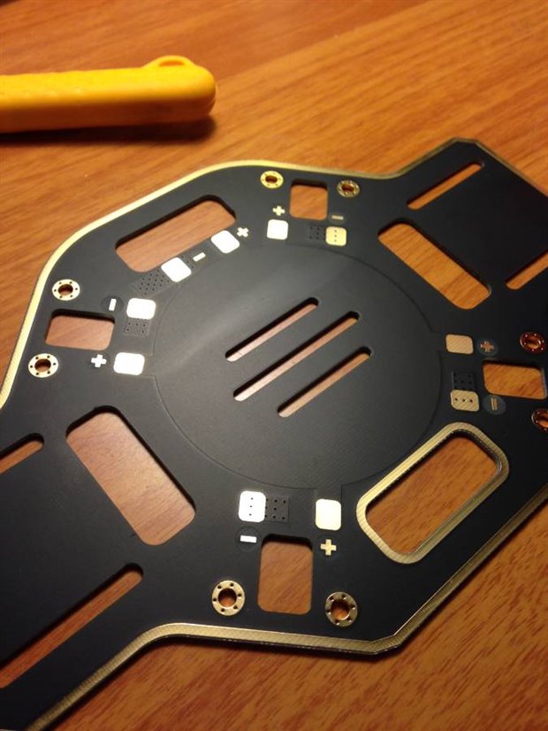
You can see here in this photo that the exposed copper is where the ESC's and battery solder to.
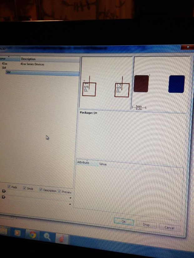
This next photo shows my attempt at creating these pads in a new library. I made the symbol, then the package, and finally married them into a device. This was my result.
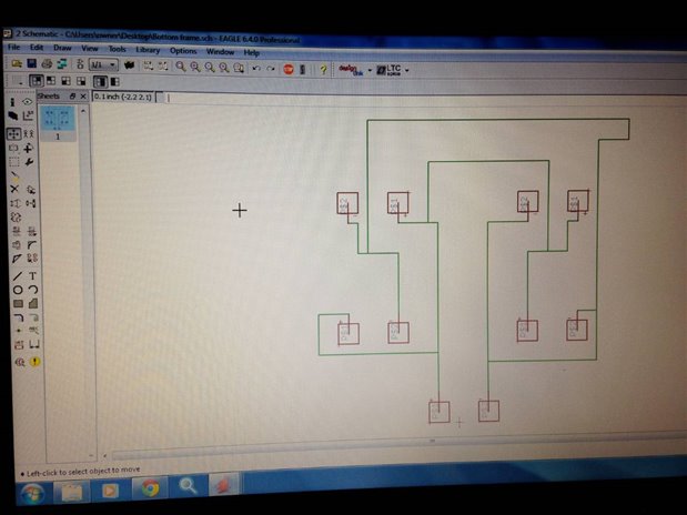
I then started to make the schematic. I took the package "SM" from the library and placed five of them on the page. 4 for the ESC's and 1 for the battery. I then took the wire tool and connected all the negative pads, and then all the positive pads being careful not to intersect them, not sure if that was necessary. This was the result.
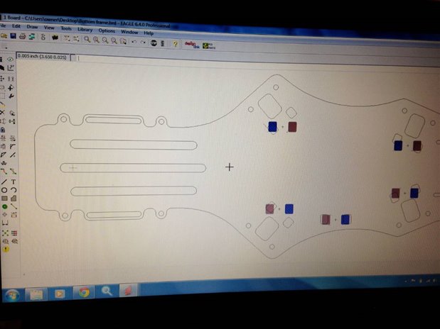
I then switched into the "board" view to where I already imported the .dxf outline of the lower quadcopter frame. I then dragged the pad sets that I made into the rough place where they needed to be. They still need to be rotated more, but they are close to where they need to be as seen below.
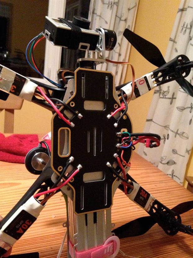
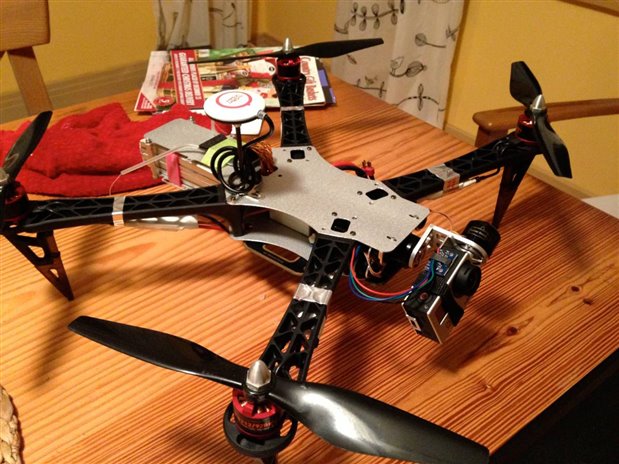
This one is just eye candy
So my main questions are if I did the schematic right or even made the package properly. If I saved this file as a gerber file, would the red pads all be positive and the blue pads be negative?
Also, there ill be quite a bit of current flowing through the wires, how do I make sure the internal wires in the board are of sufficient size?
Do need to create separate drill files, or are the holes from the .dxf file enough?
Are there PCB manufacturers who could take my raw .dxf file and some notes from me and make this board without me turning it into a gerber file?
Sorry in advance for the barrage of questions and my level of incontinence with this program.
