element14 Community
element14 Community
    Register Log In
  • Site
  • Search
  • Log In Register
  • Community Hub
    Community Hub
    • What's New on element14
    • Feedback and Support
    • Benefits of Membership
    • Personal Blogs
    • Members Area
    • Achievement Levels
  • Learn
    Learn
    • Ask an Expert
    • eBooks
    • element14 presents
    • Learning Center
    • Tech Spotlight
    • STEM Academy
    • Webinars, Training and Events
    • Learning Groups
  • Technologies
    Technologies
    • 3D Printing
    • FPGA
    • Industrial Automation
    • Internet of Things
    • Power & Energy
    • Sensors
    • Technology Groups
  • Challenges & Projects
    Challenges & Projects
    • Design Challenges
    • element14 presents Projects
    • Project14
    • Arduino Projects
    • Raspberry Pi Projects
    • Project Groups
  • Products
    Products
    • Arduino
    • Avnet Boards Community
    • Dev Tools
    • Manufacturers
    • Multicomp Pro
    • Product Groups
    • Raspberry Pi
    • RoadTests & Reviews
  • About Us
  • Store
    Store
    • Visit Your Store
    • Choose another store...
      • Europe
      •  Austria (German)
      •  Belgium (Dutch, French)
      •  Bulgaria (Bulgarian)
      •  Czech Republic (Czech)
      •  Denmark (Danish)
      •  Estonia (Estonian)
      •  Finland (Finnish)
      •  France (French)
      •  Germany (German)
      •  Hungary (Hungarian)
      •  Ireland
      •  Israel
      •  Italy (Italian)
      •  Latvia (Latvian)
      •  
      •  Lithuania (Lithuanian)
      •  Netherlands (Dutch)
      •  Norway (Norwegian)
      •  Poland (Polish)
      •  Portugal (Portuguese)
      •  Romania (Romanian)
      •  Russia (Russian)
      •  Slovakia (Slovak)
      •  Slovenia (Slovenian)
      •  Spain (Spanish)
      •  Sweden (Swedish)
      •  Switzerland(German, French)
      •  Turkey (Turkish)
      •  United Kingdom
      • Asia Pacific
      •  Australia
      •  China
      •  Hong Kong
      •  India
      •  Korea (Korean)
      •  Malaysia
      •  New Zealand
      •  Philippines
      •  Singapore
      •  Taiwan
      •  Thailand (Thai)
      • Americas
      •  Brazil (Portuguese)
      •  Canada
      •  Mexico (Spanish)
      •  United States
      Can't find the country/region you're looking for? Visit our export site or find a local distributor.
  • Translate
  • Profile
  • Settings
Altium CircuitStudio
  • Products
  • Manufacturers
  • Altium CircuitStudio
  • More
  • Cancel
Altium CircuitStudio
Altium CircuitStudio Forum Associating a footprint with a schematic Symbol
  • Blog
  • Forum
  • Documents
  • Events
  • Polls
  • Members
  • Mentions
  • Sub-Groups
  • Tags
  • More
  • Cancel
  • New
Join Altium CircuitStudio to participate - click to join for free!
Actions
  • Share
  • More
  • Cancel
Forum Thread Details
  • State Not Answered
  • Locked Locked
  • Replies 2 replies
  • Subscribers 88 subscribers
  • Views 1762 views
  • Users 0 members are here
  • frontpage
Related
This discussion has been locked.
You can no longer post new replies to this discussion. If you have a question you can start a new discussion

Associating a footprint with a schematic Symbol

mtarca
mtarca over 8 years ago

Hi,


I recently got started with Circuit Studio. I watched all of the youtube tutorials available and walked through the process of creating that oscillator circuit. I then watched the ElementI4 video on creating components in circuit studio.


There seems to be something quite key missing: how to associate a schematic symbol and footprint.


This is what I have done so far:


1) Created a new project for myself that includes a single schematic document (.SchDoc) and PCB document (.CSPcbDoc)

2) Created a new .SchLib and created a schematic symbol (with 8 pins) as described in the ElementI4 video

3) Created a new .PcbLib and created a 8-pad footprint with guidance from the same ElementI4 video.


By going to the libraries tab while viewing my schematic document, I can see in the "Project" tab that the 2 libraries I created are there. Furthermore, I can select the schematic library I created and place the new schematic symbol down on my schematic... great! However, there is no footprint associated with it.


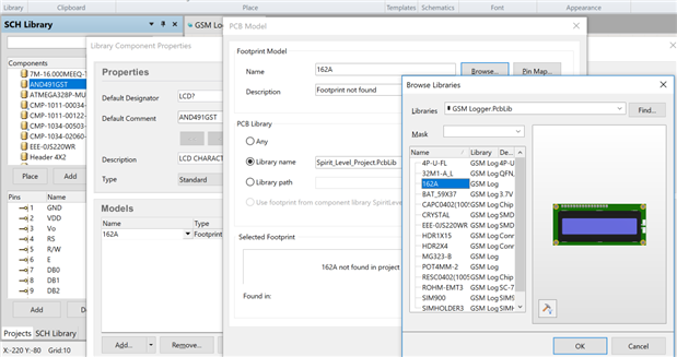
I went back to the .SchLib, found the one part I created, and went to its properties. There I see that in the "MODELS" section you can "Add -> Footprint". (Strangely, footprint is listed twice here in this dropdown menu). Either way, I select add footprint. From that menu I am able to specify the library path of the .PcbLib I created the footprint in, however it is unable to find a component (see attached image). I figured by this step I would be able to simply select a footprint and associate it with this schematic symbol.


How can I simply associate a footprint with a schematic symbol?


Thanks

Attachments:
image
  • Cancel

Top Replies

  • shishupal
    shishupal over 7 years ago in reply to jamesharrimanaltium +1
    i created the account just to say ....thank you very much.
Parents
  • jamesharrimanaltium
    0 jamesharrimanaltium over 8 years ago

    Hi Matthew,


    You have figured it out and are so close to linking it. In your screenshot you will need to click Browse in order to select the model you require from the library. This will replace "Model Name" with the name of your footprint and the link will be done.


    Save the SchLib.


    If you've already placed the symbol onto your schematic then you'll need to update that symbol with the one that includes the footprint model(s). To do this, while the SchLib document is open, right click on the component name and choose Update Schematic Sheets. The schematics that you have open at the time will be updated with the new component.


    The component will retain the same designator like R1 that you've already assigned and it will stay at the same rotation, but its Parameters and Models will be updated to reflect your updated library component.


    image


    In my screen capture, this is from the example project GSM Logger. The LCD display footprint 162A is originally from the Spririt_Level_Project.PcbLib footprint library. However because that library isn't available, I've clicked on the Browse button. Since the GSM Logger.PcbLib library is is the same project, it has automatically loaded into the dialog.


    I've clicked 162A in the library, to display the footprint.


    The PCB Model dialog currently shows "162A not found in project" but when I click OK to close the Browse Libraries dialog it will replace the other library and will display correctly in the dialog.


    Best regards,


    James Harriman

    Altium

    • Cancel
    • Vote Up 0 Vote Down
    • Cancel
  • shishupal
    0 shishupal over 7 years ago in reply to jamesharrimanaltium

    i created the account just to say ....thank you very much.

    • Cancel
    • Vote Up +1 Vote Down
    • Cancel
Reply
  • shishupal
    0 shishupal over 7 years ago in reply to jamesharrimanaltium

    i created the account just to say ....thank you very much.

    • Cancel
    • Vote Up +1 Vote Down
    • Cancel
Children
No Data
element14 Community

element14 is the first online community specifically for engineers. Connect with your peers and get expert answers to your questions.

  • Members
  • Learn
  • Technologies
  • Challenges & Projects
  • Products
  • Store
  • About Us
  • Feedback & Support
  • FAQs
  • Terms of Use
  • Privacy Policy
  • Legal and Copyright Notices
  • Sitemap
  • Cookies

An Avnet Company © 2025 Premier Farnell Limited. All Rights Reserved.

Premier Farnell Ltd, registered in England and Wales (no 00876412), registered office: Farnell House, Forge Lane, Leeds LS12 2NE.

ICP 备案号 10220084.

Follow element14

  • X
  • Facebook
  • linkedin
  • YouTube