element14 Community
element14 Community
    Register Log In
  • Site
  • Search
  • Log In Register
  • Community Hub
    Community Hub
    • What's New on element14
    • Feedback and Support
    • Benefits of Membership
    • Personal Blogs
    • Members Area
    • Achievement Levels
  • Learn
    Learn
    • Ask an Expert
    • eBooks
    • element14 presents
    • Learning Center
    • Tech Spotlight
    • STEM Academy
    • Webinars, Training and Events
    • Learning Groups
  • Technologies
    Technologies
    • 3D Printing
    • FPGA
    • Industrial Automation
    • Internet of Things
    • Power & Energy
    • Sensors
    • Technology Groups
  • Challenges & Projects
    Challenges & Projects
    • Design Challenges
    • element14 presents Projects
    • Project14
    • Arduino Projects
    • Raspberry Pi Projects
    • Project Groups
  • Products
    Products
    • Arduino
    • Avnet Boards Community
    • Dev Tools
    • Manufacturers
    • Multicomp Pro
    • Product Groups
    • Raspberry Pi
    • RoadTests & Reviews
  • About Us
  • Store
    Store
    • Visit Your Store
    • Choose another store...
      • Europe
      •  Austria (German)
      •  Belgium (Dutch, French)
      •  Bulgaria (Bulgarian)
      •  Czech Republic (Czech)
      •  Denmark (Danish)
      •  Estonia (Estonian)
      •  Finland (Finnish)
      •  France (French)
      •  Germany (German)
      •  Hungary (Hungarian)
      •  Ireland
      •  Israel
      •  Italy (Italian)
      •  Latvia (Latvian)
      •  
      •  Lithuania (Lithuanian)
      •  Netherlands (Dutch)
      •  Norway (Norwegian)
      •  Poland (Polish)
      •  Portugal (Portuguese)
      •  Romania (Romanian)
      •  Russia (Russian)
      •  Slovakia (Slovak)
      •  Slovenia (Slovenian)
      •  Spain (Spanish)
      •  Sweden (Swedish)
      •  Switzerland(German, French)
      •  Turkey (Turkish)
      •  United Kingdom
      • Asia Pacific
      •  Australia
      •  China
      •  Hong Kong
      •  India
      •  Korea (Korean)
      •  Malaysia
      •  New Zealand
      •  Philippines
      •  Singapore
      •  Taiwan
      •  Thailand (Thai)
      • Americas
      •  Brazil (Portuguese)
      •  Canada
      •  Mexico (Spanish)
      •  United States
      Can't find the country/region you're looking for? Visit our export site or find a local distributor.
  • Translate
  • Profile
  • Settings
Altium CircuitStudio
  • Products
  • Manufacturers
  • Altium CircuitStudio
  • More
  • Cancel
Altium CircuitStudio
Altium CircuitStudio Forum How to eliminate warnings about and display of power pins on components with multiple parts
  • Blog
  • Forum
  • Documents
  • Events
  • Polls
  • Members
  • Mentions
  • Sub-Groups
  • Tags
  • More
  • Cancel
  • New
Join Altium CircuitStudio to participate - click to join for free!
Actions
  • Share
  • More
  • Cancel
Forum Thread Details
  • State Suggested Answer
  • Locked Locked
  • Replies 8 replies
  • Answers 1 answer
  • Subscribers 91 subscribers
  • Views 4342 views
  • Users 0 members are here
  • multi-part
  • power pin
Related
This discussion has been locked.
You can no longer post new replies to this discussion. If you have a question you can start a new discussion

How to eliminate warnings about and display of power pins on components with multiple parts

lamabrew
lamabrew over 7 years ago

I'm pretty sure I've overlooked something obvious.


As an example, place an op-amp from Vault. After placing the A part CS seems to switch to placing the B part for you. However it shows power pins too:

image

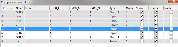
Same thing if you also place each part from Vault. If you compile the schematic it throws Duplicate Pin warnings about the power pins. If I open up the properties for the B part and edit the pins and hide the power pins the warnings go away, but the symbol still shows pins:


image


My questions:

  • Is there a way to have CS automatically not include power pins after the first sub-part is placed?
  • Is there a way to remove/hide the extra lines like shown on the B part above?


Thanks

  • Cancel
  • e14softwareuk
    0 e14softwareuk over 7 years ago

    Typically a multi-part symbol like this will be defined either with the power pins on all sub-parts or with a separate sub-part just for power. In your example each sub-part has power pins, you should not need to try and delete or hide them. Once all are wired up (same duplicate pin numbers to same net) the duplicate pin warning will disappear.

    • Cancel
    • Vote Up 0 Vote Down
    • Cancel
  • jimku
    0 jimku over 7 years ago

    I have created schematic symbols with multiple parts with power pins on only one of the parts and have never had a problem with the power pins showing up on the other parts. Something that I think that I am doing differently from what you describe is that I place the power pins on the last gate of the multi-part part. I just briefly tried it again to see what would happen or if something changed since the last time I created a multi-part symbol but it worked fine as expected. When I created the schematic symbol I created part A without power pins. I then created part B and then added the power pins. Compile and save. I then place part A first in the schematic and then part B. I do the same with multi-part logic where I create all the parts without the power pins and add the power pins to the last symbol of the multi-part device. Power pins then show up only once per multi-part device which is the last part of the package.

    • Cancel
    • Vote Up 0 Vote Down
    • Cancel
  • lamabrew
    0 lamabrew over 7 years ago in reply to e14softwareuk

    These are parts from Vault. The power pins are on Part 0, which from the docs seems like the right way to set power up for a component with multiple parts.I tried several and it seems they are all done like that.

    image


    IMHO wiring all of the power pins on each of the sub-parts would be 'wrong' on many levels.


    I have not tried creating a component with multiple parts yet (hey there's another tutorial topic image ). But since Vault components can't be modified Jim's method to 'fix' this problem wouldn't help.


    Now I'm wondering if Is this a bug in Circuit Studio (i.e. follow the documentation about placing power on part 0 and get an incorrect result)?

    • Cancel
    • Vote Up 0 Vote Down
    • Cancel
  • jimku
    0 jimku over 7 years ago in reply to lamabrew

    I overlooked your first message in that you were talking about components from the vault. After reading your latest message I went back and discovered that I could put the power pins on any part and they will “only” show up on that part so it doesn’t matter which part I attach the power pins to. If I use the “Component Pin Editor” and change the Owner of the power pins to “0” then the power pins show up on “all” of the parts of the package.


    I downloaded the OPA1612AIDR from the vault and see what you are talking about. I haven’t tried it all the way to compile but I was able to use the “Component Pin Editor” on each of the OPA1612 parts and change the Owner to “1” and the power pins will only show up on that part. The other part still shows a stub of a power pin but I think that is due to it being drawn with a simple poly-line to have the power pins extend all the way to the triangle of the symbol. If this works, it would only be a work around when using Vault components with multi-parts. I agree with you in that the power pins should not be on all of the sub-parts. I used Vault components on my first design with CircuitStudio and didn’t like some of the way the symbols were drawn so I now create all my symbols and use the free “Library Expert Lite” to create footprints from manufacturers data sheets.


    I searched briefly for the documentation about placing power on part 0 and couldn’t find it. Do you have a link? I have never used the “Component Pin Editor” when creating parts since most of that information can be edited in the properties dialog while placing pins (except for creating an owner 0).

    • Cancel
    • Vote Up 0 Vote Down
    • Cancel
  • lamabrew
    0 lamabrew over 7 years ago in reply to jimku

    Hi Jim,

    Thanks for digging in to this. I'm new to Altium so never quite sure if it's me or the tool...


    The comment about the part 0 came from: Pin Properties | Online Documentation for Altium Products  but when I re-read it maybe that note in blue is talking about hardcoding a net name to the pin (boy that would be bad idea if so) and not power pins in general?


    I do notice that with the pin hidden the warning goes away; not sure which is the better choice (hide vs. move to the last part).


    I didn't think to check the symbol that the lines were put of the graphic. I guess I live with that for now but hopefully Altium comes up with a more conventional way to deal with this. I'm really trying to stay out of the component making business as much as possible image

    • Cancel
    • Vote Up 0 Vote Down
    • Cancel
  • jimku
    0 jimku over 7 years ago in reply to lamabrew

    I checked out the page you referenced and see where they talk about the part number field and using it for power pins and assigning it to “0”. I don’t want to spend the time trying to figure out exactly what they are saying but it says in the “connect” field to typically specify a power net but in the blue box below it says to enable “Hide” and leave the “connect” field blank. If you leave it blank, how does it know what power net to connect to? It’s also a little confusing that they call it a “part number” field in the Pin Properties window but it’s called “owner” in the Component Pin Editor window. Yeah, power pins on multi-part devices were connected in this hidden fashion when I first started using CAD in the early 90s but never understood why someone would want to do this. Maybe it’s just a tale but I have heard of logic gates drawn that way not even having their power pins connected at all due to the part being incorrectly created. The logic gate actually worked most of the time by getting power from its input lines from the input protection diodes that are normally part of CMOS and other components. As long as the inputs had at least one high level and one low level input to any of the inputs the part worked as expected but if all of the inputs happen to be all high or all low at the same time the part would malfunction. It was a bear (difficult) to troubleshoot the problem. From that story, my colleagues and I have always had the power pins explicitly shown and connected to their appropriate power net. Logic gate power got even be more confusing when circuits started using 3.3V instead of 5V.


    Another thing that I did experience first-hand in my group (again in the early 90s) was in using the supplied library component for an LM324 (I think that was the part) was one of the four op-amps had its plus and minus inputs reversed. From this experience, I have always gone back and double checked the pin out for even supplied library parts (but I almost always create my own parts anyhow).


    As far as what you are doing, I don’t know if one way is better than the other (hide vs. move). As long as the power pins are connected to their proper power nets somewhere, it shouldn’t matter. Whatever way you decide, just be sure to verify they are connected in the layout.

    • Cancel
    • Vote Up 0 Vote Down
    • Cancel
  • e14softwareuk
    0 e14softwareuk over 7 years ago in reply to jimku

    Jim, this is exactly how I used to create multi-part symbols. Define all the gates then have a power part and perhaps other common / misc pins. However the parts in question are vault parts which cannot easily be modified so I think either stick with how the vault works and wire up all the power pins to eliminate the compiler warnings or define your own parts in whatever style you wish.

    • Cancel
    • Vote Up 0 Vote Down
    • Cancel
  • gervasi
    0 gervasi over 6 years ago

    Have you tried changing the "Part Number" field on the power pins in the Properties panel?  If the value is 0, the pins appear on all sub-parts.  If you change it to "1", it just appears on the first sub-part.

    image

    • Cancel
    • Vote Up 0 Vote Down
    • Cancel
element14 Community

element14 is the first online community specifically for engineers. Connect with your peers and get expert answers to your questions.

  • Members
  • Learn
  • Technologies
  • Challenges & Projects
  • Products
  • Store
  • About Us
  • Feedback & Support
  • FAQs
  • Terms of Use
  • Privacy Policy
  • Legal and Copyright Notices
  • Sitemap
  • Cookies

An Avnet Company © 2025 Premier Farnell Limited. All Rights Reserved.

Premier Farnell Ltd, registered in England and Wales (no 00876412), registered office: Farnell House, Forge Lane, Leeds LS12 2NE.

ICP 备案号 10220084.

Follow element14

  • X
  • Facebook
  • linkedin
  • YouTube