I extracted the sources of an intlib component ( a 16 pin header).I edited the sch and pcb to make an 12 pin header and then compiled the part into a new intlib.
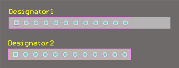
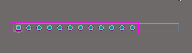
I placed the part on my schematic, and pulled the part onto the PCB. The sch part and the PCB footprint look correct, but the footprint also includes the "keepout" area from the original 16 pin part
causing the part to turn red when it interferes with another part. See attached jpg.
How can I edit the keepout area to match the 12 pins?
Many thanks,
yassirreebob
Attachments:
 |