element14 Community
element14 Community
    Register Log In
  • Site
  • Search
  • Log In Register
  • Community Hub
    Community Hub
    • What's New on element14
    • Feedback and Support
    • Benefits of Membership
    • Personal Blogs
    • Members Area
    • Achievement Levels
  • Learn
    Learn
    • Ask an Expert
    • eBooks
    • element14 presents
    • Learning Center
    • Tech Spotlight
    • STEM Academy
    • Webinars, Training and Events
    • Learning Groups
  • Technologies
    Technologies
    • 3D Printing
    • FPGA
    • Industrial Automation
    • Internet of Things
    • Power & Energy
    • Sensors
    • Technology Groups
  • Challenges & Projects
    Challenges & Projects
    • Design Challenges
    • element14 presents Projects
    • Project14
    • Arduino Projects
    • Raspberry Pi Projects
    • Project Groups
  • Products
    Products
    • Arduino
    • Avnet Boards Community
    • Dev Tools
    • Manufacturers
    • Multicomp Pro
    • Product Groups
    • Raspberry Pi
    • RoadTests & Reviews
  • Store
    Store
    • Visit Your Store
    • Choose another store...
      • Europe
      •  Austria (German)
      •  Belgium (Dutch, French)
      •  Bulgaria (Bulgarian)
      •  Czech Republic (Czech)
      •  Denmark (Danish)
      •  Estonia (Estonian)
      •  Finland (Finnish)
      •  France (French)
      •  Germany (German)
      •  Hungary (Hungarian)
      •  Ireland
      •  Israel
      •  Italy (Italian)
      •  Latvia (Latvian)
      •  
      •  Lithuania (Lithuanian)
      •  Netherlands (Dutch)
      •  Norway (Norwegian)
      •  Poland (Polish)
      •  Portugal (Portuguese)
      •  Romania (Romanian)
      •  Russia (Russian)
      •  Slovakia (Slovak)
      •  Slovenia (Slovenian)
      •  Spain (Spanish)
      •  Sweden (Swedish)
      •  Switzerland(German, French)
      •  Turkey (Turkish)
      •  United Kingdom
      • Asia Pacific
      •  Australia
      •  China
      •  Hong Kong
      •  India
      •  Korea (Korean)
      •  Malaysia
      •  New Zealand
      •  Philippines
      •  Singapore
      •  Taiwan
      •  Thailand (Thai)
      • Americas
      •  Brazil (Portuguese)
      •  Canada
      •  Mexico (Spanish)
      •  United States
      Can't find the country/region you're looking for? Visit our export site or find a local distributor.
  • Translate
  • Profile
  • Settings
Altium CircuitStudio
  • Products
  • Manufacturers
  • Altium CircuitStudio
  • More
  • Cancel
Altium CircuitStudio
Altium CircuitStudio Forum How to Create Jumper Wires in Schematics for Clarity
  • Blog
  • Forum
  • Documents
  • Events
  • Polls
  • Members
  • Mentions
  • Sub-Groups
  • Tags
  • More
  • Cancel
  • New
Altium CircuitStudio requires membership for participation - click to join
Actions
  • Share
  • More
  • Cancel
Forum Thread Details
  • State Verified Answer
  • Locked Locked
  • Replies 7 replies
  • Subscribers 85 subscribers
  • Views 3044 views
  • Users 0 members are here
Related
This discussion has been locked.
You can no longer post new replies to this discussion. If you have a question you can start a new discussion

How to Create Jumper Wires in Schematics for Clarity

sysy019
sysy019 over 1 year ago

Hello,

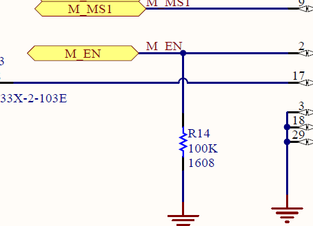
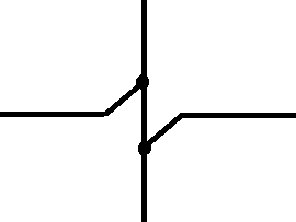
I'm currently working on a schematic in Circuit Studio and seeking to improve its readability. I noticed in some schematics, like the attached image, that jumper wires are used to clearly indicate where wires cross without connecting. In my current schematic, the lines simply cross each other, which can be visually confusing.

Could someone guide me on how to create these jumper wires or implement a similar feature to enhance the clarity of my schematic? Any tips or procedures for visually distinguishing crossing wires would be greatly appreciated.

Thank you for your help!

image

  • Cancel

Top Replies

  • GabeFromSpace
    GabeFromSpace over 1 year ago +4 verified
    Go under File >> System Preferences (the button at the bottom) >> Schematic >> General >> Display Cross-Overs
  • Jan Cumps
    Jan Cumps over 1 year ago +4
    Related: when I studied electronics and learned to draw schematics, a "crossing connection" was not allowed. Connections had to be T nodes. A T node is always a connection Crossing wires is always…
  • beacon_dave
    beacon_dave over 1 year ago in reply to Jan Cumps +3
    I always used to do this, so it is clear that it is a join and not a crossing.
  • GabeFromSpace
    +1 GabeFromSpace over 1 year ago

    Go under File >> System Preferences (the button at the bottom) >> Schematic >> General >> Display Cross-Overs

    • Cancel
    • Vote Up +4 Vote Down
    • Cancel
  • Jan Cumps
    0 Jan Cumps over 1 year ago

    Related: when I studied electronics and learned to draw schematics, a "crossing connection" was not allowed. Connections had to be T nodes.

    • A T node is always a connection
    • Crossing wires is always a cross, never a node

    One of the advantages is that crosses and jump hoops may become blurred, and look similar,  when you resize schematic bitmaps (or in the days: when you xerox a schematic). 

    • Cancel
    • Vote Up +4 Vote Down
    • Cancel
  • wolfgangfriedrich
    0 wolfgangfriedrich over 1 year ago in reply to Jan Cumps

    This is the correct way to do connections and crossing. Combined with a very strong effort to minimize crossings as much as possible, you get very readable schematics. 

    Example above: one could route the signal going to 'pin17' below R14 and the GND symbol. 

    • Cancel
    • Vote Up +1 Vote Down
    • Cancel
  • Andrew J
    0 Andrew J over 1 year ago in reply to Jan Cumps

    I (sort of) agree here and find it clearer without the curves.  I wouldn’t necessarily define it purely as a T node though: a wire could connect and then continue to connect to another of the same net.  It’s the dot or blob that defines a connection even at a T junction, although it would be easy to argue that a wire that arrives at another and doesn’t continue is almost certainly connected or an error - although the EDA program is likely to complain in an ERC check if a wire just stops without the blob.  So a wire that crosses without the blob is not connected and it’s definitely worth going with the flow on this one as it would help in reading other’s schematics.

    • Cancel
    • Vote Up +1 Vote Down
    • Cancel
  • Jan Cumps
    0 Jan Cumps over 1 year ago in reply to Andrew J
    Andrew J said:
    t’s the dot or blob that defines a connection even at a T junction

    It works well if you can maintain the resolution of the image. Once it's a bitmap or a printout, every cross will start looking as if there's (maybe) a dot eventually. 

    Here's how The AOE draws:

    image

    • Cancel
    • Vote Up +2 Vote Down
    • Cancel
  • beacon_dave
    0 beacon_dave over 1 year ago in reply to Jan Cumps

    I always used to do this, so it is clear that it is a join and not a crossing.

    image

    • Cancel
    • Vote Up +3 Vote Down
    • Cancel
  • jpnbino
    0 jpnbino over 1 year ago in reply to beacon_dave

    I used that one too. It surely helped me.

    • Cancel
    • Vote Up +1 Vote Down
    • Cancel
element14 Community

element14 is the first online community specifically for engineers. Connect with your peers and get expert answers to your questions.

  • Members
  • Learn
  • Technologies
  • Challenges & Projects
  • Products
  • Store
  • About Us
  • Feedback & Support
  • FAQs
  • Terms of Use
  • Privacy Policy
  • Legal and Copyright Notices
  • Sitemap
  • Cookies

An Avnet Company © 2025 Premier Farnell Limited. All Rights Reserved.

Premier Farnell Ltd, registered in England and Wales (no 00876412), registered office: Farnell House, Forge Lane, Leeds LS12 2NE.

ICP 备案号 10220084.

Follow element14

  • X
  • Facebook
  • linkedin
  • YouTube