Hello,
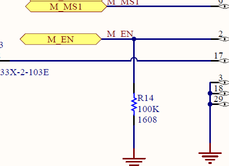
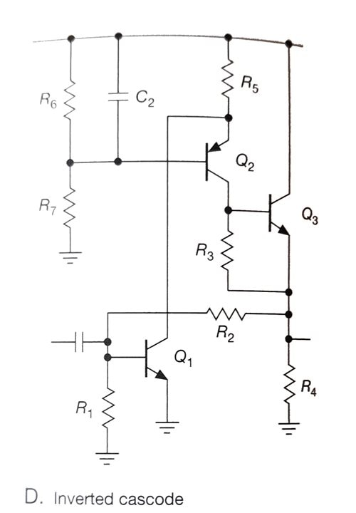
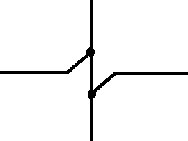
I'm currently working on a schematic in Circuit Studio and seeking to improve its readability. I noticed in some schematics, like the attached image, that jumper wires are used to clearly indicate where wires cross without connecting. In my current schematic, the lines simply cross each other, which can be visually confusing.
Could someone guide me on how to create these jumper wires or implement a similar feature to enhance the clarity of my schematic? Any tips or procedures for visually distinguishing crossing wires would be greatly appreciated.
Thank you for your help!


