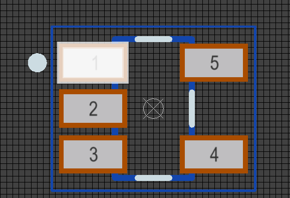
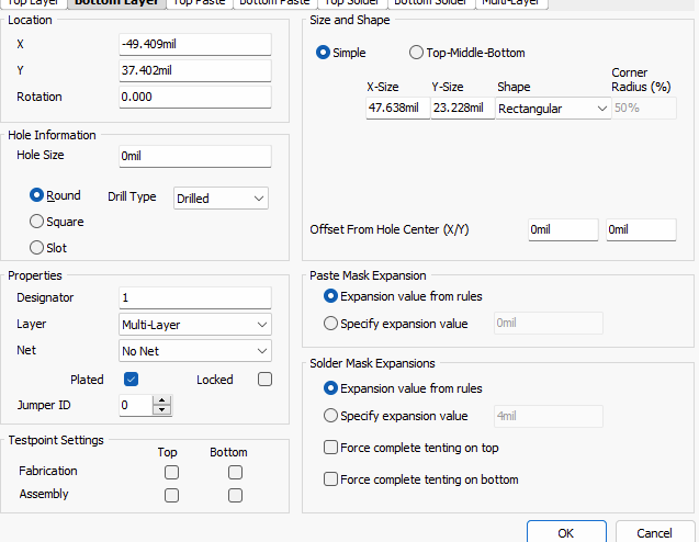
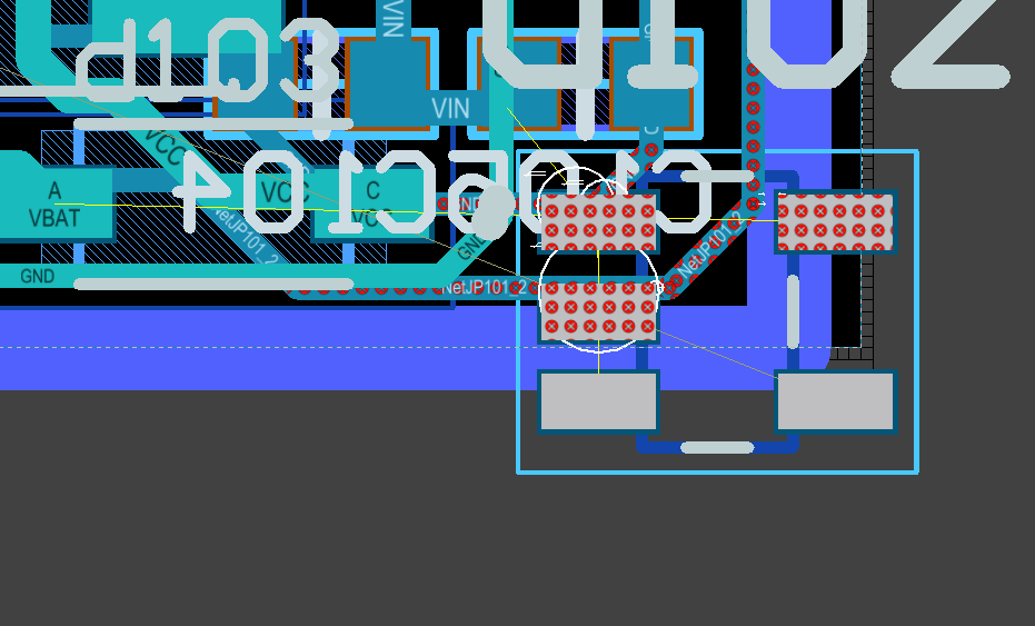
The below info is a test just to prove my issue, but in short the SMD thinks its a thru hole on the PCB.
Here I put it on the edge where there are no conflicts on the layer I put it on
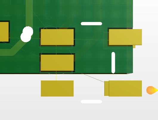
here is the 3d view
...
I had to make my own sch library files but the foot print was available. I made my own sch and then added the foot print. But when adding to my PCB it conflicts on the under side layer. It looks likes pads are drawn on both side.
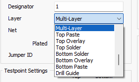
I see no way to draw pads on both layer in the editor how was that done?
