element14 Community
element14 Community
    Register Log In
  • Site
  • Search
  • Log In Register
  • About Us
  • Community Hub
    Community Hub
    • What's New on element14
    • Feedback and Support
    • Benefits of Membership
    • Personal Blogs
    • Members Area
    • Achievement Levels
  • Learn
    Learn
    • Ask an Expert
    • eBooks
    • element14 presents
    • Learning Center
    • Tech Spotlight
    • STEM Academy
    • Webinars, Training and Events
    • Learning Groups
  • Technologies
    Technologies
    • 3D Printing
    • FPGA
    • Industrial Automation
    • Internet of Things
    • Power & Energy
    • Sensors
    • Technology Groups
  • Challenges & Projects
    Challenges & Projects
    • Design Challenges
    • element14 presents Projects
    • Project14
    • Arduino Projects
    • Raspberry Pi Projects
    • Project Groups
  • Products
    Products
    • Arduino
    • Avnet Boards Community
    • Dev Tools
    • Manufacturers
    • Multicomp Pro
    • Product Groups
    • Raspberry Pi
    • RoadTests & Reviews
  • Store
    Store
    • Visit Your Store
    • Choose another store...
      • Europe
      •  Austria (German)
      •  Belgium (Dutch, French)
      •  Bulgaria (Bulgarian)
      •  Czech Republic (Czech)
      •  Denmark (Danish)
      •  Estonia (Estonian)
      •  Finland (Finnish)
      •  France (French)
      •  Germany (German)
      •  Hungary (Hungarian)
      •  Ireland
      •  Israel
      •  Italy (Italian)
      •  Latvia (Latvian)
      •  
      •  Lithuania (Lithuanian)
      •  Netherlands (Dutch)
      •  Norway (Norwegian)
      •  Poland (Polish)
      •  Portugal (Portuguese)
      •  Romania (Romanian)
      •  Russia (Russian)
      •  Slovakia (Slovak)
      •  Slovenia (Slovenian)
      •  Spain (Spanish)
      •  Sweden (Swedish)
      •  Switzerland(German, French)
      •  Turkey (Turkish)
      •  United Kingdom
      • Asia Pacific
      •  Australia
      •  China
      •  Hong Kong
      •  India
      •  Korea (Korean)
      •  Malaysia
      •  New Zealand
      •  Philippines
      •  Singapore
      •  Taiwan
      •  Thailand (Thai)
      • Americas
      •  Brazil (Portuguese)
      •  Canada
      •  Mexico (Spanish)
      •  United States
      Can't find the country/region you're looking for? Visit our export site or find a local distributor.
  • Translate
  • Profile
  • Settings
Altium CircuitStudio
  • Products
  • Manufacturers
  • Altium CircuitStudio
  • More
  • Cancel
Altium CircuitStudio
Altium CircuitStudio Forum Variant Issues
  • Blog
  • Forum
  • Documents
  • Events
  • Polls
  • Members
  • Mentions
  • Sub-Groups
  • Tags
  • More
  • Cancel
  • New
Join Altium CircuitStudio to participate - click to join for free!
Actions
  • Share
  • More
  • Cancel
Forum Thread Details
  • Locked Locked
  • Replies 11 replies
  • Subscribers 88 subscribers
  • Views 2360 views
  • Users 0 members are here
Related
This discussion has been locked.
You can no longer post new replies to this discussion. If you have a question you can start a new discussion

Variant Issues

adamwebber
adamwebber over 8 years ago

I am working with variants in CS.  I have declared the variant options to show the RED X on the schematics when parts are not fitted.  However, when I select the variant with not fitted parts, only the PCB is affected.  The schematics do not change.  How do I set it up so that it shows not fitted parts on both the schematic and PCB?  Rather, how do I display the RED X for not fitted components on the schematics?


My current steps:

1-Open Variant Manager

2-Add Variant

3-Name the Variant

4-Click OK

5-Select components "Not Fitted" in variant

6-Make sure that the variant options are selected in the schematic and PCB.

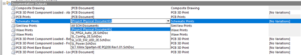
7-In Project Actions, select variant from drop-down menu. 

8-Watch as the schematic does not change.

9-Watch as the PCB changes by making components disappear.


This is also the case when generating outputs.  I can only generate the No Variant output of the schematics.  The PCB works though.

Attachments:
image
image
image
  • Cancel

Top Replies

  • harvie256
    harvie256 over 8 years ago in reply to e14softwareteam +1
    So the answer the question I asked... No Circuitstudio does not support multi-channel Variants like Altium Designer has for the last few generations. That's a shame, I use hierarchical multi-channel schematics…
  • vaidasmm
    vaidasmm over 8 years ago in reply to jamesharrimanaltium +1
    Thank You very much, now it works just fine .
Parents
  • e14softwareteam
    e14softwareteam over 8 years ago

    From the developers:


    Home > Project > Compile will compile the schematic and add the Compiler Tab at the bottom left of the schematic, adjacent to the Editor tab. Click the Compiler tab and the Not Fitted components will display the red X (provided the Drawing Style hasn't been changed to not show it) over the component.

    When Generating Outputs, for Schematic Prints you must click the Configure link and change from Logical Documents to Physical Documents. This is so that the software doesn't just print out the schematics as they were edited, but rather the compiled version for the Variant you're saving to PDF.

    Think of Physical as what will be physically present on the PCB.

    • Cancel
    • Vote Up 0 Vote Down
    • Cancel
  • vaidasmm
    vaidasmm over 8 years ago in reply to e14softwareteam

    How to change these physical to logical documents? Because I can't print pdf without not fitted components...

    • Cancel
    • Vote Up 0 Vote Down
    • Cancel
  • jamesharrimanaltium
    jamesharrimanaltium over 8 years ago in reply to vaidasmm

    Hi Vaidas,


    The Schematic Prints can be configured in the Generate outputs dialog. Choose the variant at the top and click the Configure link to open the properties. Set the type to Physical Documents. Then when the PDF is generated, the red X will display.


    image


    Best regards,


    James Harriman

    Altium

    • Cancel
    • Vote Up 0 Vote Down
    • Cancel
  • vaidasmm
    vaidasmm over 8 years ago in reply to jamesharrimanaltium

    Thank You for the reply, but I forgot to tell, that I am using Altium designer, not CircuitStudio (I was expecting, that it is everything the same), but Altium designer in "Schematic print properties" does not have this field with physical document...

    • Cancel
    • Vote Up 0 Vote Down
    • Cancel
  • jamesharrimanaltium
    jamesharrimanaltium over 8 years ago in reply to vaidasmm

    Hi Viadas,


    In Altium Designer you need to use an Outjob and choose [Project Physical Documents] as the Data Source.


    image


    Best regards,


    James Harriman

    Altium

    • Cancel
    • Vote Up 0 Vote Down
    • Cancel
Reply
  • jamesharrimanaltium
    jamesharrimanaltium over 8 years ago in reply to vaidasmm

    Hi Viadas,


    In Altium Designer you need to use an Outjob and choose [Project Physical Documents] as the Data Source.


    image


    Best regards,


    James Harriman

    Altium

    • Cancel
    • Vote Up 0 Vote Down
    • Cancel
Children
  • vaidasmm
    vaidasmm over 8 years ago in reply to jamesharrimanaltium

    Thank You very much, now it works just fine image.

    • Cancel
    • Vote Up +1 Vote Down
    • Cancel
element14 Community

element14 is the first online community specifically for engineers. Connect with your peers and get expert answers to your questions.

  • Members
  • Learn
  • Technologies
  • Challenges & Projects
  • Products
  • Store
  • About Us
  • Feedback & Support
  • FAQs
  • Terms of Use
  • Privacy Policy
  • Legal and Copyright Notices
  • Sitemap
  • Cookies

An Avnet Company © 2025 Premier Farnell Limited. All Rights Reserved.

Premier Farnell Ltd, registered in England and Wales (no 00876412), registered office: Farnell House, Forge Lane, Leeds LS12 2NE.

ICP 备案号 10220084.

Follow element14

  • X
  • Facebook
  • linkedin
  • YouTube