element14 Community
element14 Community
    Register Log In
  • Site
  • Search
  • Log In Register
  • Community Hub
    Community Hub
    • What's New on element14
    • Feedback and Support
    • Benefits of Membership
    • Personal Blogs
    • Members Area
    • Achievement Levels
  • Learn
    Learn
    • Ask an Expert
    • eBooks
    • element14 presents
    • Learning Center
    • Tech Spotlight
    • STEM Academy
    • Webinars, Training and Events
    • Learning Groups
  • Technologies
    Technologies
    • 3D Printing
    • FPGA
    • Industrial Automation
    • Internet of Things
    • Power & Energy
    • Sensors
    • Technology Groups
  • Challenges & Projects
    Challenges & Projects
    • Design Challenges
    • element14 presents Projects
    • Project14
    • Arduino Projects
    • Raspberry Pi Projects
    • Project Groups
  • Products
    Products
    • Arduino
    • Avnet Boards Community
    • Dev Tools
    • Manufacturers
    • Multicomp Pro
    • Product Groups
    • Raspberry Pi
    • RoadTests & Reviews
  • Store
    Store
    • Visit Your Store
    • Choose another store...
      • Europe
      •  Austria (German)
      •  Belgium (Dutch, French)
      •  Bulgaria (Bulgarian)
      •  Czech Republic (Czech)
      •  Denmark (Danish)
      •  Estonia (Estonian)
      •  Finland (Finnish)
      •  France (French)
      •  Germany (German)
      •  Hungary (Hungarian)
      •  Ireland
      •  Israel
      •  Italy (Italian)
      •  Latvia (Latvian)
      •  
      •  Lithuania (Lithuanian)
      •  Netherlands (Dutch)
      •  Norway (Norwegian)
      •  Poland (Polish)
      •  Portugal (Portuguese)
      •  Romania (Romanian)
      •  Russia (Russian)
      •  Slovakia (Slovak)
      •  Slovenia (Slovenian)
      •  Spain (Spanish)
      •  Sweden (Swedish)
      •  Switzerland(German, French)
      •  Turkey (Turkish)
      •  United Kingdom
      • Asia Pacific
      •  Australia
      •  China
      •  Hong Kong
      •  India
      •  Korea (Korean)
      •  Malaysia
      •  New Zealand
      •  Philippines
      •  Singapore
      •  Taiwan
      •  Thailand (Thai)
      • Americas
      •  Brazil (Portuguese)
      •  Canada
      •  Mexico (Spanish)
      •  United States
      Can't find the country/region you're looking for? Visit our export site or find a local distributor.
  • Translate
  • Profile
  • Settings
Altium CircuitStudio
  • Products
  • Manufacturers
  • Altium CircuitStudio
  • More
  • Cancel
Altium CircuitStudio
Altium CircuitStudio Forum dwg/dxf into schematic document
  • Blog
  • Forum
  • Documents
  • Events
  • Polls
  • Members
  • Mentions
  • Sub-Groups
  • Tags
  • More
  • Cancel
  • New
Join Altium CircuitStudio to participate - click to join for free!
Actions
  • Share
  • More
  • Cancel
Forum Thread Details
  • Locked Locked
  • Replies 11 replies
  • Subscribers 87 subscribers
  • Views 1972 views
  • Users 0 members are here
Related
This discussion has been locked.
You can no longer post new replies to this discussion. If you have a question you can start a new discussion

dwg/dxf into schematic document

slowertech
slowertech over 8 years ago

Does anyone know if it is possible to import a dwg or dxf into a schematic drawing?


Thanks

  • Cancel
  • tarribred61
    tarribred61 over 8 years ago

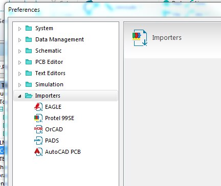
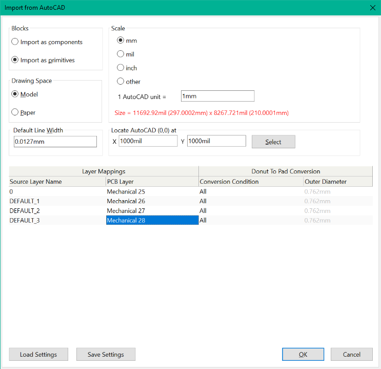
    Do you mean into a PCB document?  The PCB has an import function for DWG and DXF but I don't know what restrictions such as versions it can accept.  This function brings up a window to Import from AutoCAD and you enter the layer mappings and scale.


    If you attempt to import a DWG or DXF into a schematic it will instead open a PCB document and attempt the import.

    • Cancel
    • Vote Up 0 Vote Down
    • Cancel
  • slowertech
    slowertech over 8 years ago in reply to tarribred61

    Thanks


    I have been using the PCB import for irregular board shapes.

    I was hoping to import some connectors for documenting a cable assembly and have been unable to figure out if I can import to schematics.

    • Cancel
    • Vote Up 0 Vote Down
    • Cancel
  • e14softwareuk
    e14softwareuk over 8 years ago

    It is correct that you can only import DXF onto a PCB, not directly onto a schematic. However it is possible using the copy/paste functionality.


    You may need to play around with line widths, scaling and layers when importing the DXF. Once imported select the items of interest, click Copy, switch to the schematic sheet and click Paste. Don't forget to make sure you have the DXF import package installed otherwise nothing will appear to happen when importing.

    • Cancel
    • Vote Up 0 Vote Down
    • Cancel
  • slowertech
    slowertech over 8 years ago in reply to e14softwareuk

    Just tried it and it works!


    Thanks!!

    • Cancel
    • Vote Up 0 Vote Down
    • Cancel
  • tarribred61
    tarribred61 over 8 years ago in reply to slowertech

    However, for cables you can cut and paste in screen shots so if you have photos of the cable or connectors you can add them to help document what you want someone to do.  For example, make it clear the connections are from wiring side view and not the connection side view.


    This can also be useful to show reworks to a schematic/PCB as an inset on the schematic.

    • Cancel
    • Vote Up 0 Vote Down
    • Cancel
  • jimmallabar
    jimmallabar over 7 years ago in reply to e14softwareuk

    Hi Peter,


    This is not exactly related to he original post, but how do I install the .dxf importer.  When I go to File->Import .dxf is an option, but .dxf is not listed  in my system preferences.

    image

    Thanks,

    Jim

    • Cancel
    • Vote Up 0 Vote Down
    • Cancel
  • e14softwareuk
    e14softwareuk over 7 years ago in reply to jimmallabar

    You may need to install the DXF importer, this is supplied with CircuitStudio but may not have installed automatically.From another post on the issue (note the file path will depend on where you chose to install CircuitStudio)


    "You may need to uninstall/reinstall the installation of TeighaX, the installer is located at C:\Program Files (x86)\Altium\CS\System\Installation\TeighaX_Setup_3.9.0.msi. TeighaX is a 3rd party utility used during import of dxf/dwg."


    Also check View > Start (Home) > My Account > Extensions & Updates : Configure... to see a list of installed importers and make sure DXF is selected.

    • Cancel
    • Vote Up 0 Vote Down
    • Cancel
  • jimmallabar
    jimmallabar over 7 years ago in reply to e14softwareuk

    Thanks for the post, but it still did not work.


    I had run C:\Program Files (x86)\Altium\CS\System\Installation\TeighaX_Setup_3.9.0.msi yesterday.  I think I had found the post you quoted from.

    I checked "My Acount > Extentions & Updates" and found "DXF and DWG" is checked.  Do I need to have that unchecked when I install the TeigaX utility?


    Am I performing the right steps?


    1. I go to a blank PCB.
    2. File > Import and navigate to my DXF file
    3. I've tried all combinations of Blocks (components/primitives) and Drawing Space (Model/Paper)/
    4. I've selected several Scale options, "inch" makes the size the correct size, but the text turns red when I do that.
    5. image
    6. I've tried a couple of options for Layer Mapping, from leaving it all as default to setting all Source Layers to PCB "Layer Mechanical 3"
    7. I always get an Information Box indicating "Done".
    8. After I click "OK" I get a little spinning wheel for several seconds, and then nothing.  None of the mechanical layers indicate that that they are used.

    Can you send me a known good DXF?  All the ones I have are generated by SolidWorks (various versions from 2010 to 2017).


    Thanks for your help

    Jim

    • Cancel
    • Vote Up 0 Vote Down
    • Cancel
  • tarribred61
    tarribred61 over 7 years ago in reply to jimmallabar

    Sounds like we need a precursor blog example for the one named "working-with-dxf-board-outlines-in-circuitstudio"


    Creating a board outline from DXF in CircuitStudio

    • Cancel
    • Vote Up 0 Vote Down
    • Cancel
  • tarribred61
    tarribred61 over 7 years ago in reply to tarribred61

    The attached dxf file as a zip (if it goes through) should be able to import as the following settings.  The source layer 0 is the only one with information.  The other layers don't seem to have anything on them.  You can see I imported them into different mechanical layers.  Hopefully, you know the scaling of your DXF.

    image


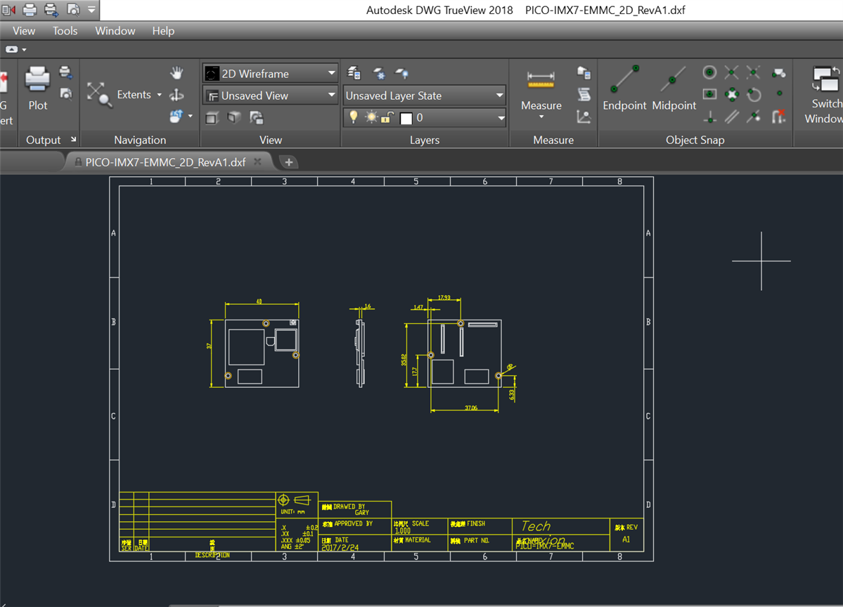
    If you look at this in AutoCad or Autodesk DWG TrueView you will see something like below.

    image


    This came to me from a vendor that makes single board computers.  The sheet symbol, text and module outlines are dimensions end up on the same layer.  That's not ideal but it is at least an example you can try.  After I import this, the text is askew.  However the line art for the board outline and dimensions appear correctly.


    After import into CS I get this...

    image

    • Cancel
    • Vote Up 0 Vote Down
    • Cancel
>
element14 Community

element14 is the first online community specifically for engineers. Connect with your peers and get expert answers to your questions.

  • Members
  • Learn
  • Technologies
  • Challenges & Projects
  • Products
  • Store
  • About Us
  • Feedback & Support
  • FAQs
  • Terms of Use
  • Privacy Policy
  • Legal and Copyright Notices
  • Sitemap
  • Cookies

An Avnet Company © 2025 Premier Farnell Limited. All Rights Reserved.

Premier Farnell Ltd, registered in England and Wales (no 00876412), registered office: Farnell House, Forge Lane, Leeds LS12 2NE.

ICP 备案号 10220084.

Follow element14

  • X
  • Facebook
  • linkedin
  • YouTube