

CircuitStudio version at time of writing : 1.5.1
The CircuitStudio PCB editor provides a facility for importing DXF files which if often used to bring in board outlines but can also be used to import other information. The import allows assigning drawing data to user selected layers so the process is very flexible. It is not well documented that the import process can alter the board shape (the one seen in 3D View, the black board area on the grey workspace). For more background information please see our article Creating a board outline from DXF in CircuitStudio.
To import a DXF file use File > Import... and then select file type AutoCAD PCB Files (*.DXF; *.DWG). The import dialog that follows allows assigning layers in the drawing to layers in your PCB document and allows setting how the imported data is scaled.
Once the import completed you may find your board shape has been redefined. How it is altered is a little complex and depends on the layers imported and existing design data.
Preserving your existing board shape
If you had a defined board shape and wish to keep it then the follow method allows you to save a copy (before importing) and then restore that copy (once import completed).
Step #1: Run Home | Board Shape > Create Primitives From Board Shape
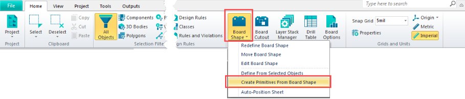

The layer you save the primitives to should be a spare layer not currently used for anything else. It is easiest to select Delete Existing so that you can easily select the generated primitives when re-creating the board.
Step #2: Import your DXF data.
Step #3: Restore your board shape by selecting the primitives from the first step and then running Home | Board Shape > Define From Selected Objects. To make it easier to select the primitives you can going into single layer mode with View | Single Layer Mode, select the Outline (or other layer used for saving the primitives) as the current layer (bottom tabs in editor window) and then selecting all items on the layer with Home | Select > All.
How your board shape may change
Assuming there is no data on the Keep-Out layer...
- The board shape will be extended to incorporate the newly imported objects.
- If there are components or similar that were outside the board area the board will be extended to include these.
- The board shape will be a rectangle (bounding all objects).
If there is data on the Keep-Out Layer...
- The board shape will try to take on the shape of any enclosed object on the Keep-Out Layer.
- If there are multiple shapes on Keep-Out then the board shape may become a bounding rectangle enclosing the shapes.
- The board outline may be undefined (does not exist) sometimes.
It is common to have a copy of the board outline on the Keep-Out Layer, often a thick outline that acts to keep tracks and components within the defined board area. If you are importing DXF onto another layer then it can happen your board outline will expand slightly on each DXF import because the board will be re-defined from the outer bounds of the keepout.
If you import DXF onto the Keep-Out Layer...
- Acts very much like above where you can assume the DXF data was already on the Keep-Out Layer. In particular if you import and enclosed shape and there were no other shapes on the Keep-Out Layer you will most likely end up with a board outline matching (or approximating) the imported data.
In Summary
Even though it may almost seem sensible of the software to use the Keep-Out Layer to recreate the board shape automatically in practice the outer edge of the outline is used and so the board outline will change. The motto of this story is to keep a copy of your board outline on a spare layer so that it's there in case you need it to re-create your board. Typically the Outline layer is used in Gerber generation and contains a copy of the board outline so this can be a good layer to make use of.
Alternative Workflow
A CircuitStudio user suggested an alternative workflow which is very much worth mentioning (thanks bugrobotics). Instead of importing directly into your PCB create a spare PCB document and work with that to perform the imports and then simply copy/paste across to the real design afterwards. This minimises any possibility of your real design getting altered unexpectedly.