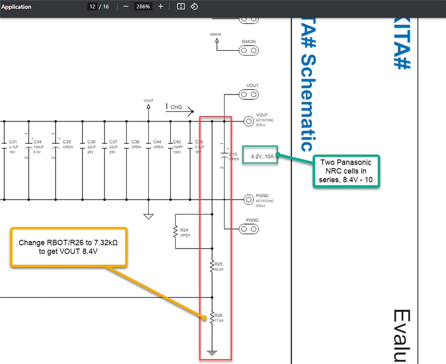


C34 looks like a problem waiting to happen it's only rated at 6.3V. It is worth replacing this but I would be surprised if its causing the problem you describe.
Can't guess what else is wrong.
Do be very careful if the batteries get hot - that could be very dangerous.
Try putting a scope on the output (and maybe other places) - if the charger is unstable and oscillating it won't work right.
The data sheet talks about a capacitor across Rbot but I don't see one on your schematic - there is one on the eval board but it may be the wrong value now.
MK
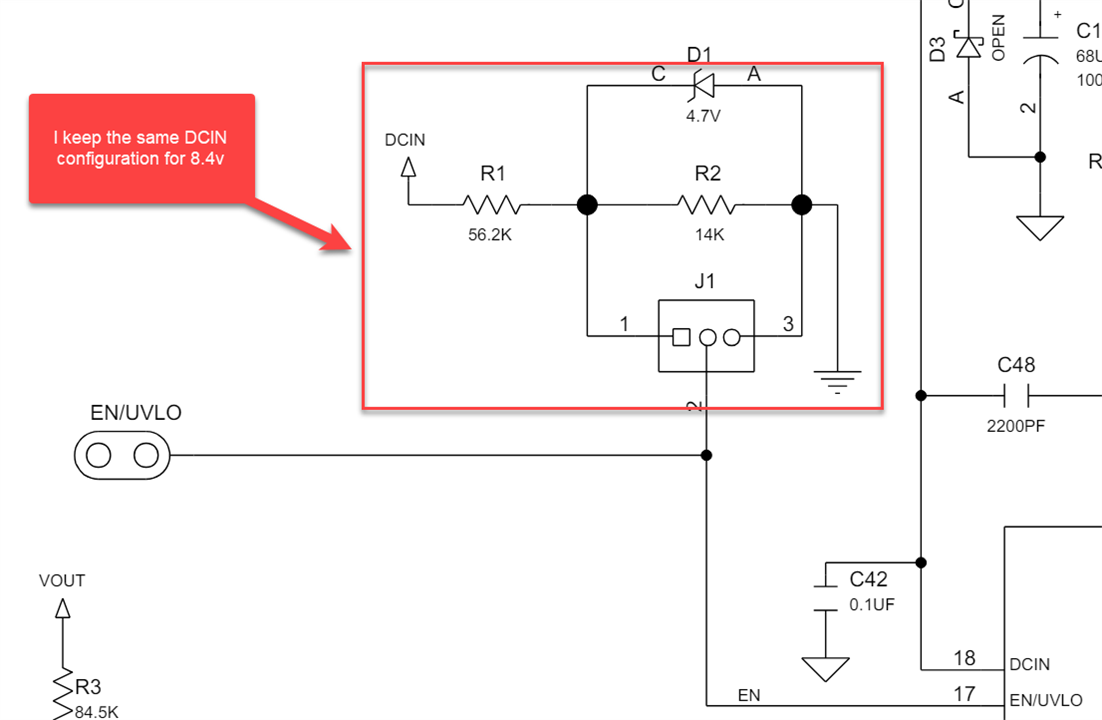
HI, Thank you for the reply. Firstly, I am having an issue related to the input side. The output capacitor C34, which you highlighted, has a 20% tolerance. I cross-verified this capacitor, and it is not causing the issue. It has 8.4V consistently with no heating issues related to this tantalum capacitor. The issue I am facing is related to the input side. The kit is designed for an input range of 6.3V to 60V, but my kit only starts at 14.2V or greater. This is the problem. I cross-verified everything, and the EN/UVLO IC pin has 2.8V when it turns on. However, below this, the kit does not start. Once the kit starts at 14.2V, it continues to work even if I reduce the voltage to below 14.2V, such as 11V or 10.5V. Initially, we require more voltage to turn on the kit.
If you are over-volting a tantalum capacitor then expect a fire !
It WILL fail. Generally good practice is to use tantalum capacitors at no more than 50% of their voltage rating.
How do you know that that there is no oscillation on the output side which prevents the 17703 from starting ?
Does anything at all happen on the output side ?
Did your board work correctly before you modified it ?
MK
Yes, I actually verified this in two ways. First, I cross verified by connecting an oscilloscope, C34 is not oscillating too much or not even heating. Then, I removed C34 from the kit, as it only provides filtration, and checked again to turn on the kit. However, the same issue persists, so it clearly means the issue is something else.
I have also noticed that many people have the same issue with this IC related to power. Most people are asking about this problem on different platforms regarding the 17703, and all have similar issues. Previously, my kit was heating up too. Do you think this is a hardware-related issue? Because everything seems perfectly alright regarding the calculations, and the devkit datasheet states that if we change the Vout voltages, only certain components need to be redesigned, and they haven't mentioned anything related to C34. Do you suggest another charging kit that can charge lithium-ion batteries at 8.4V with 10A to 20A? I have looked into this BMS. Could you please provide your insights on this as well?
prodcut link: https://es.aliexpress.com/i/4000032444415.html?gatewayAdapt=glo2esp

What state are the fault flags in ?
MK
When I connect below 14V, both Flag 1 and Flag 2 show 0V, which means the charger is turned off. ISMON reads 0.1v or lower considered noisy voltages when the charger is off. The charger doesn't respond even if the batteries are completely discharged or their voltages drop below 7.8V. It stays off until I provide 14.2V or higher. when I forcefully turn on the kit with 14.2V input, Flag 2 shows 5.1V and Flag 1 shows 0V, indicating that charging is happening. The battery voltages quickly rise to their maximum of 8.4V. Initially, ISMON reads 1.4V to 1.2V, but then stabilizes around 0.8V or 0.9V, showing a charging current of 6A to 5.33A. Charging continues, and sometimes the batteries start heating when they are deeply discharged. This heating only happens in this specific case. Once the batteries are charged to around 7.4V or 7.8V, they do not heat up.
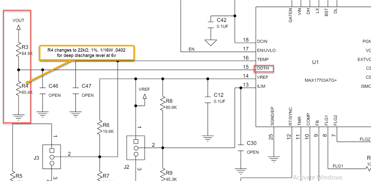
Hello, Regarding the input voltage calculation for the kit power on, your configuration seems appropriate when using a single 4.2V cell. However, with two cells in series, the minimum voltage level should be adjusted accordingly. For reference, please use the formula provided in the MAX17703DEVKIT datasheet on page 26 under "Setting the Input Undervoltage-Lockout Level (EN/UVLO)" This adjustment is necessary for proper protection. Addressing your primary concern, if the kit only initiates at voltages above 14V and causes battery heating, it indicates a potential internal fault. While the kit is operational, the forced start at higher voltages suggests internal damage. It is advisable to either replace the kit to avoid potential burnout issues. Be cautious, as this could be dangerous. Moreover, if the kit's fault detection mechanism is not triggering under these conditions, it implies that the kit's timer is functioning correctly. However, the lack of fault generation in your scenario points towards an internal defect.
Thanks for the response. Could you please clarify one more thing related to battery temperature? The datasheet for this kit mentions that we can operate it with a battery temperature from 45 to 50c max. I am using 18650 lithium ion panasonic NRC-18650B cells in my application, which is automotive related. The device is placed in a truck where the atmospheric temperature can exceed 50c, could you please suggest another kit suitable for those conditions? or do you think we can place this kit in such conditions?
Hello,
The data sheet clearly states the temperature range, stating that you cannot exceed these limits. Please be careful, as you are dealing with batteries that can be dangerous at high temperatures.