element14 Community
element14 Community
    Register Log In
  • Site
  • Search
  • Log In Register
  • About Us
  • Community Hub
    Community Hub
    • What's New on element14
    • Feedback and Support
    • Benefits of Membership
    • Personal Blogs
    • Members Area
    • Achievement Levels
  • Learn
    Learn
    • Ask an Expert
    • eBooks
    • element14 presents
    • Learning Center
    • Tech Spotlight
    • STEM Academy
    • Webinars, Training and Events
    • Learning Groups
  • Technologies
    Technologies
    • 3D Printing
    • FPGA
    • Industrial Automation
    • Internet of Things
    • Power & Energy
    • Sensors
    • Technology Groups
  • Challenges & Projects
    Challenges & Projects
    • Design Challenges
    • element14 presents Projects
    • Project14
    • Arduino Projects
    • Raspberry Pi Projects
    • Project Groups
  • Products
    Products
    • Arduino
    • Avnet Boards Community
    • Dev Tools
    • Manufacturers
    • Multicomp Pro
    • Product Groups
    • Raspberry Pi
    • RoadTests & Reviews
  • Store
    Store
    • Visit Your Store
    • Choose another store...
      • Europe
      •  Austria (German)
      •  Belgium (Dutch, French)
      •  Bulgaria (Bulgarian)
      •  Czech Republic (Czech)
      •  Denmark (Danish)
      •  Estonia (Estonian)
      •  Finland (Finnish)
      •  France (French)
      •  Germany (German)
      •  Hungary (Hungarian)
      •  Ireland
      •  Israel
      •  Italy (Italian)
      •  Latvia (Latvian)
      •  
      •  Lithuania (Lithuanian)
      •  Netherlands (Dutch)
      •  Norway (Norwegian)
      •  Poland (Polish)
      •  Portugal (Portuguese)
      •  Romania (Romanian)
      •  Russia (Russian)
      •  Slovakia (Slovak)
      •  Slovenia (Slovenian)
      •  Spain (Spanish)
      •  Sweden (Swedish)
      •  Switzerland(German, French)
      •  Turkey (Turkish)
      •  United Kingdom
      • Asia Pacific
      •  Australia
      •  China
      •  Hong Kong
      •  India
      •  Korea (Korean)
      •  Malaysia
      •  New Zealand
      •  Philippines
      •  Singapore
      •  Taiwan
      •  Thailand (Thai)
      • Americas
      •  Brazil (Portuguese)
      •  Canada
      •  Mexico (Spanish)
      •  United States
      Can't find the country/region you're looking for? Visit our export site or find a local distributor.
  • Translate
  • Profile
  • Settings
Analog Devices
  • Products
  • Manufacturers
  • Analog Devices
  • More
  • Cancel
Analog Devices
Forum Cannot maintain a constant PWM - only get about 10 cycles out of my DS1050-025
  • Blog
  • Forum
  • Documents
  • Events
  • Polls
  • Members
  • Mentions
  • Sub-Groups
  • Tags
  • More
  • Cancel
  • New
Join Analog Devices to participate - click to join for free!
Actions
  • Share
  • More
  • Cancel
Forum Thread Details
  • State Verified Answer
  • Replies 19 replies
  • Subscribers 39 subscribers
  • Views 548 views
  • Users 0 members are here
Related

Cannot maintain a constant PWM - only get about 10 cycles out of my DS1050-025

dfansler
dfansler 1 month ago

Hi Andy - 

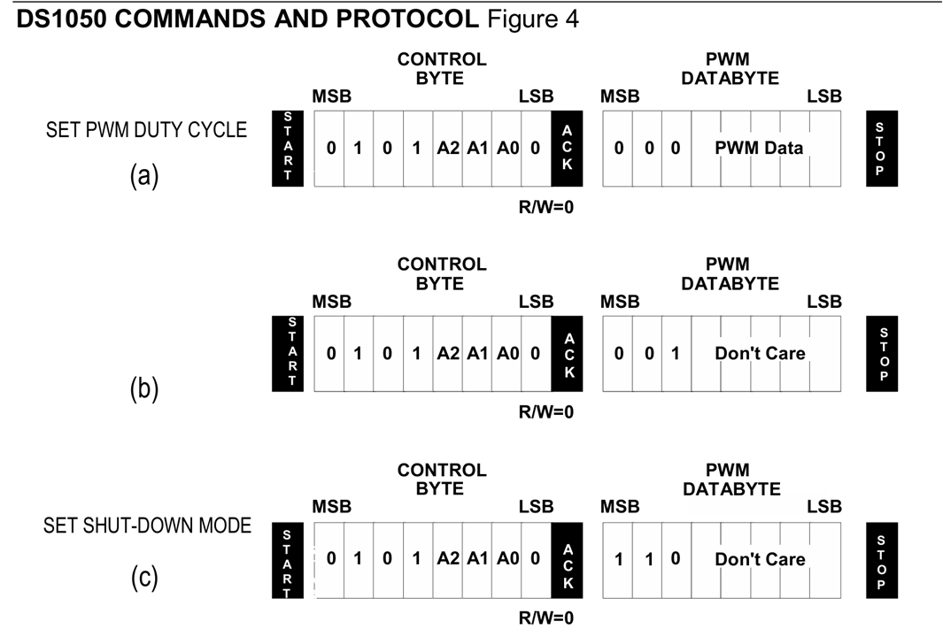
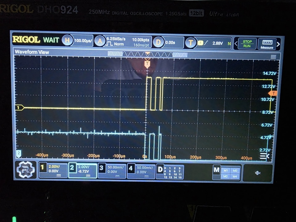
 I had my DS1050-025 running, for a while, but now I can only get about 3 to 10 cycles out it.  I have gone back over changes I have made, but nothing seems to help.  Here is the test code I am currently trying.  I open the DS1050 i2c, using address 0x28 ( as shown by i2cdetect on my Raspberry Pi, which this hardware is on).  Then I write 0x50 (set PMW command) followed by the data (shown as 0x10h - which should be 50% PWM).

I close the file descriptor, call the second function, where I open the DS1050 in i2c again, writing 0x50 (set PWM command) followed by the data 0x20 as shown on the DS1050 data sheet.  Then again close the file descriptor.  I have tried combining the two functions and write 0x50, 0x10, 0x50, 0x20 and the close i2c with the same results.

#include <stdio.h>
#include <stdlib.h>
#include <math.h>
#include "/home/dvf/glg/include/GlgApi.h"
#include <sys/types.h>
#include <sys/stat.h>
#include <fcntl.h>
#include <unistd.h>    // read/write usleep     
#include <inttypes.h>  // uint8_t, etc
#include <linux/i2c-dev.h> // I2C bus definitions
#include <sys/ioctl.h>			//Needed for I2C port
#include "/home/dvf/glg/include/GlgApi.h"
#include <sys/socket.h>
#include <netinet/in.h>
#include <string.h>
#include <arpa/inet.h>


#include <termios.h>

#include <stdio.h>
#include <sys/types.h> // open
#include <sys/stat.h>  // open
#include <fcntl.h>     // open
#include <unistd.h>    // read/write usleep
#include <stdlib.h>    // exit
#include <inttypes.h>  // uint8_t, etc
#include <linux/i2c-dev.h> // I2C bus definitions
#include <sys/ioctl.h>
#include "PWM.h"
int PWM_Write2(void);
int fd_pwm, fd;
   int16_t val;
   uint8_t writeBuf[5], readBuf[2];

void main(void)
{
   

   // open device on /dev/i2c-1 
   if ((fd_pwm = open("/dev/i2c-1", O_RDWR)) < 0) 
   {
      printf("Error: Couldn't open I2C device\n");
      return;
   }

   // connect to ads1115 as i2c slave
   if (ioctl(fd_pwm, I2C_SLAVE, PWM_Addrs) < 0)
    {
      printf("Error: Couldn't find device on address!\n");
      return;
   }
   // set config register and start conversion

   writeBuf[0] = SetPWM;    // config register is 1
   writeBuf[1] = 0x10;
  // Set newm PWM duty
   if (write(fd_pwm, writeBuf, 4) != 4) 
   {
       printf("Can't write to register 1\n");
       return;
   }

   close(fd_pwm);

   PWM_Write2();
   while(1)
{
   ;
}

}

int PWM_Write2(void)
{
   // open device on /dev/i2c-1 
   if ((fd = open("/dev/i2c-1", O_RDWR)) < 0) {
      printf("Error: Couldn't open I2C device\n");
      return 1;
   }
printf("fd = %d\n",fd);
   // connect to ads1115 as i2c slave
   if (ioctl(fd, I2C_SLAVE, PWM_Addrs) < 0) {
      printf("Error: Couldn't find device on address!\n");
      return 1;
   }
// set config register and start conversion

   writeBuf[0] = SetPWM;    // config register is 1
   writeBuf[1] = 0x20;
   // Set newm PWM duty
   if (write(fd, writeBuf, 2) != 2) 
   {
       printf("Can't write to register 1\n");
       return 1;
   }

	close(fd);
}

image

Hope you can help,

David
YouTube "Sailing Solo at 70"

  • Sign in to reply
  • Cancel

Top Replies

  • dfansler
    dfansler 1 month ago in reply to Andrew J +4 verified
    Hi Andrew and Dave - thanks for your comments. The cyan trace is in inverse of the yellow trace - my motor controller requires two PWM signals that are the inverse of each other. I see the problem…
  • dfansler
    dfansler 1 month ago +3
    I just tried out my $9 Logic Analyzer that the software has an I2C Analyzer - I am blown away (Amazon Title "1 Set USB Logic Analyzer Device Set 8 Channel 24 MHz UART SPI Debug Logical Analysis Device…
  • dfansler
    dfansler 1 month ago in reply to dfansler +1
    Here is the link to the free software- https://www.saleae.com/pages/downloads - for the $9 logic analyzer, with Analyzers for I2C, SPI and UART. David
Parents
  • Andrew J
    0 Andrew J 1 month ago

    Perhaps I’ve missed something but you are sending 0x20 as data which is 0b00100000 but the data byte only allows for 5 bits (which are all 0).  If you look at page 11 of the data sheet, sending 0b00100000 tells the device to ignore the data bits (it’s effectively a NOP command). What is the data value you are actually trying to send?

    • Cancel
    • Vote Up +1 Vote Down
    • Sign in to reply
    • Verify Answer
    • Cancel
  • beacon_dave
    0 beacon_dave 1 month ago in reply to Andrew J

    0x20 is the command to "Set PWM duty cycle 100%"

    image

    • Cancel
    • Vote Up +1 Vote Down
    • Sign in to reply
    • Verify Answer
    • Cancel
  • Andrew J
    0 Andrew J 1 month ago in reply to beacon_dave

    Ah ok, makes sense.  That is shown in the logic analyser output so it looks like all is working.

    • Cancel
    • Vote Up 0 Vote Down
    • Sign in to reply
    • Verify Answer
    • Cancel
  • beacon_dave
    0 beacon_dave 1 month ago in reply to Andrew J

    If you look at the scope trace, it transitions from 50% to 100% as per the commands but then after around 450us it transitions to 0%. The logic analyser capture stops before it transitions to 0% so can't see if there was another command sent or not to cause this.

    • Cancel
    • Vote Up 0 Vote Down
    • Sign in to reply
    • Verify Answer
    • Cancel
  • Andrew J
    0 Andrew J 1 month ago in reply to beacon_dave

    Trace 2, cyan, shows the start of something that coincides with the drop from 100%.  Is it reasonable to assume the two are connected, trace of SCL perhaps?  I expect the LA trace was taken at a different time to the scope trace but it would be useful to see it synchronised across the problem.  However, it would be good  for the OP to come back with more info as to what he/she expects to see.

    • Cancel
    • Vote Up 0 Vote Down
    • Sign in to reply
    • Verify Answer
    • Cancel
  • dfansler
    +1 dfansler 1 month ago in reply to Andrew J

    Hi Andrew and Dave - thanks for your comments.

    The cyan trace is in inverse of the yellow trace - my motor controller requires two PWM signals that are the inverse of each other.

    I see the problem now - when you look at the data sheet on page 11, the first command (a) is to SetPWM, the second command (b) has no label and I thought it was a continuation of the SetPWM command, since the rest of the commands have labels!

    I dropped the second command and all is well - the PWM works as expected.

    Many thanks for the help.

    The PWM is part of an autopilot I am building for my 24' cuddy cabin boat "Dragon Seeker".  The USCG sank my 50' sailboat (Dragon Fire) some 15 miles off the coast of Virginia Beach, VA.  I am headed out this week to find and raise Dragon Fire.  Once up, I will be using Dragon Seeker to push Dragon Fire about 70 miles south in the Atlantic to Oregan Inlet and then some 90 miles to a boat yard near Washington, NC.  The autopilot will allow me to do work on Dragon Fire while underway,  AND keep me from having to steer Dragon Seeker manually for the trip - which will probably take 2 to 3 days.  You can see the out come on YouTube at "Sailing Solo at 70" (although I am 74 now).  I purchased Dragon Fire in Greece in 2022 and sailed it solo from Greece to North Carolina.

    Again, thanks for the help.

    David

    image

    • Cancel
    • Vote Up +4 Vote Down
    • Sign in to reply
    • Verify Answer
    • Reject Answer
    • Cancel
  • Jan Cumps
    0 Jan Cumps 1 month ago in reply to dfansler
    dfansler said:
    my motor controller requires two PWM signals that are the inverse of each other

    What controller are you using? Some require dead time between the edges of the two opposite signals.

    • Cancel
    • Vote Up 0 Vote Down
    • Sign in to reply
    • Verify Answer
    • Cancel
Reply
  • Jan Cumps
    0 Jan Cumps 1 month ago in reply to dfansler
    dfansler said:
    my motor controller requires two PWM signals that are the inverse of each other

    What controller are you using? Some require dead time between the edges of the two opposite signals.

    • Cancel
    • Vote Up 0 Vote Down
    • Sign in to reply
    • Verify Answer
    • Cancel
Children
  • dfansler
    0 dfansler 1 month ago in reply to Jan Cumps

    It is just a generic unit from Amazon.  Dual Motor Controller, 12v, 30A per Channel.  Each channel has Gnd, Pwr, In1, In2, Enable and a current output that is CT Output Voltage (V) = Current (A) x 0.155  .  Found out more about it (current per channel and CT from another website.  I have used it on small motors with inverted PWM signal with no problem.

    David 

    • Cancel
    • Vote Up +1 Vote Down
    • Sign in to reply
    • Verify Answer
    • Cancel
  • Jan Cumps
    0 Jan Cumps 1 month ago in reply to dfansler

    I checked, and this module has the deadband circuitry built-in. All good.

    • Cancel
    • Vote Up 0 Vote Down
    • Sign in to reply
    • Verify Answer
    • Cancel
element14 Community

element14 is the first online community specifically for engineers. Connect with your peers and get expert answers to your questions.

  • Members
  • Learn
  • Technologies
  • Challenges & Projects
  • Products
  • Store
  • About Us
  • Feedback & Support
  • FAQs
  • Terms of Use
  • Privacy Policy
  • Legal and Copyright Notices
  • Sitemap
  • Cookies

An Avnet Company © 2025 Premier Farnell Limited. All Rights Reserved.

Premier Farnell Ltd, registered in England and Wales (no 00876412), registered office: Farnell House, Forge Lane, Leeds LS12 2NE.

ICP 备案号 10220084.

Follow element14

  • X
  • Facebook
  • linkedin
  • YouTube