This design idea output regulation is ±1 to ±3 percent with input voltage changes of 0.3 volt or less and efficiency is approximately 94 percent.
by Joe Pierson, Cirrus Logic - Apex Precision Power
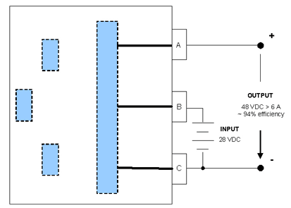
This design idea describes a novel DC-to-DC converter design concept that can be used in a variety of applications requiring conversions such as +28 volts to -48 volts (relative to the +28 V input), or -20 volts (relative to the -28 V input), while delivering a minimum of 8.5 A of combined output.
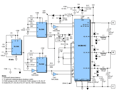
The “novel” approach to this converter design is that it utilizes a very space compact Cirrus Logic IC with a 2-cm (0.75-inch) square-footprint. The SA306-IHZ is a monolithic three-phase switching amplifier1,2 from the Apex Precision Power product family that is typically targeted at brushless motor control drives. The SA306-IHZ is depicted schematically in this converter design in Figure 1. The inputs and the outputs are depicted in Figure 2. Efficiencies of approximately 94% are realized. Transient load response is quite good with full recovery in approximately 3 milliseconds.
The drive circuit shown in Figure 1 comprises three Texas Instruments TLC555 CMOS Timers. U1 serves as a 45 kHz oscillator. It, in turn, drives U2 and U3 which can be thought of as pulse width modulators (PWMs). This design assumes a well-regulated voltage input because of limited loop gain. The output voltage regulation is ±1% to ±3% over the full output load range with an input voltage delta of 300 mV. There is no current limit circuit included for a number of reasons, one of which is that the input is diode coupled to the output — output currents in excess of 15 A will exceed the diode current/wire bond ratings.
Slow Start Circuit — If there were no constraint when start up occurs, the input current would become very high because the circuit would attempt to immediately restore the low output voltage. In order to manage this scenario, the PWM, which behaves, in effect, as an error amplifier, is prevented from overreacting and instead the duty cycle is controlled so that it rises slowly. As Vs comes up, it would normally pass through the 30 V zener diode D3 and adjustment potentiometer R8 to the junction – or duty cycle node – between Resistors R7 and R15. Instead the Soft Start node is connected directly to the output through D1 – C4 to Vs+ — thereby bypassing the output of the converter sensed by the R8 – D3 network until the Vs potential is reached.
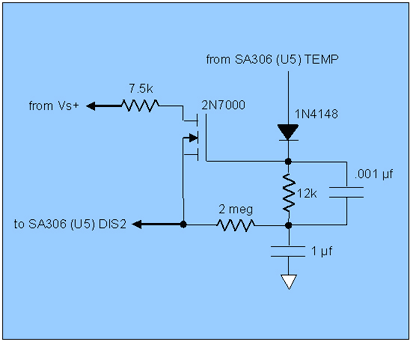
Thermal Overload Protection – Shown in Figure 3 is a circuit that could be added to temporarily remove output power from the SA306-IHZ via DIS2 if a thermal overload is detected at TEMP pin 25. An optional latch may be driven by the SA306-IHZ at TEMP pin 25 and its output could be used to shut down the converter via the DIS 1 pin 7, and/or shut down the 28 V supply in the event of a cooling failure. External current monitoring could also be gated to the same DIS1 pin 7 latch to protect the Boost Converter from load faults, etc.
As Vs comes up, it would normally pass through the 30 V zener diode D3 and adjustment potentiometer R8 to the junction – or duty cycle node – between Resistors R7 and R15. Instead the Soft Start node is connected directly to the output through D1 – C4 to Vs+ — thereby bypassing the output of the converter sensed by the R8 – D3 network until the Vs potential is reached.
Overvoltage Protection — Overvoltage protection is set by Potentiometer R9 so that limiting begins when the output reaches 57 V. The DIS2 pin 23 is employed to shut down the S306-IHZ if a 1.7 V threshold at the pin is exceeded.
Product information table:
Mftrs. Part No. |
SA306 – IHZ |
SA57 – IHZ |
SA306 – FHZ |
SA57 - FHZ |


