element14 Community
element14 Community
    Register Log In
  • Site
  • Search
  • Log In Register
  • Community Hub
    Community Hub
    • What's New on element14
    • Feedback and Support
    • Benefits of Membership
    • Personal Blogs
    • Members Area
    • Achievement Levels
  • Learn
    Learn
    • Ask an Expert
    • eBooks
    • element14 presents
    • Learning Center
    • Tech Spotlight
    • STEM Academy
    • Webinars, Training and Events
    • Learning Groups
  • Technologies
    Technologies
    • 3D Printing
    • FPGA
    • Industrial Automation
    • Internet of Things
    • Power & Energy
    • Sensors
    • Technology Groups
  • Challenges & Projects
    Challenges & Projects
    • Design Challenges
    • element14 presents Projects
    • Project14
    • Arduino Projects
    • Raspberry Pi Projects
    • Project Groups
  • Products
    Products
    • Arduino
    • Avnet Boards Community
    • Dev Tools
    • Manufacturers
    • Multicomp Pro
    • Product Groups
    • Raspberry Pi
    • RoadTests & Reviews
  • About Us
  • Store
    Store
    • Visit Your Store
    • Choose another store...
      • Europe
      •  Austria (German)
      •  Belgium (Dutch, French)
      •  Bulgaria (Bulgarian)
      •  Czech Republic (Czech)
      •  Denmark (Danish)
      •  Estonia (Estonian)
      •  Finland (Finnish)
      •  France (French)
      •  Germany (German)
      •  Hungary (Hungarian)
      •  Ireland
      •  Israel
      •  Italy (Italian)
      •  Latvia (Latvian)
      •  
      •  Lithuania (Lithuanian)
      •  Netherlands (Dutch)
      •  Norway (Norwegian)
      •  Poland (Polish)
      •  Portugal (Portuguese)
      •  Romania (Romanian)
      •  Russia (Russian)
      •  Slovakia (Slovak)
      •  Slovenia (Slovenian)
      •  Spain (Spanish)
      •  Sweden (Swedish)
      •  Switzerland(German, French)
      •  Turkey (Turkish)
      •  United Kingdom
      • Asia Pacific
      •  Australia
      •  China
      •  Hong Kong
      •  India
      •  Korea (Korean)
      •  Malaysia
      •  New Zealand
      •  Philippines
      •  Singapore
      •  Taiwan
      •  Thailand (Thai)
      • Americas
      •  Brazil (Portuguese)
      •  Canada
      •  Mexico (Spanish)
      •  United States
      Can't find the country/region you're looking for? Visit our export site or find a local distributor.
  • Translate
  • Profile
  • Settings
STMicroelectronics
  • Products
  • Manufacturers
  • STMicroelectronics
  • More
  • Cancel
STMicroelectronics
Forum HAL Libraries - Importing and Using
  • Blog
  • Forum
  • Documents
  • Events
  • Polls
  • Members
  • Mentions
  • Sub-Groups
  • Tags
  • More
  • Cancel
  • New
Join STMicroelectronics to participate - click to join for free!
Actions
  • Share
  • More
  • Cancel
Forum Thread Details
  • Replies 15 replies
  • Subscribers 14 subscribers
  • Views 11432 views
  • Users 0 members are here
  • st products
  • truestudio
  • attolic
  • stm32l476jg
Related

HAL Libraries - Importing and Using

14rhb
14rhb over 6 years ago

I'm after some advice on how to do the following, the discussion will likely be useful to others, so I have broken out to this 'fresh area'. Happy to move if there is a more suitable place.


I'm participating in Sixth Sense Design Challenge and anyone following that will likely see a few posts from me stating that I'm struggling to understand the STM32 development cycle more than the actual range of IDEs. My initial discussion is https://www.element14.com/community/community/design-challenges/sixth-sense-design-challenge/blog/2019/02/25/r2b4-6-sens…


I'm currently using True Studio and STM32L476 although the question could easily relate to the other IDE  and/or other devices and boards. I can, with some effort and luck, manage to install and download the examples that are provided in the relevant STM32xx_Cube downloads, I can use STM32xxCubeMX to make a skeleton framework but I seem lost when it comes to adding into an existing project.


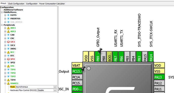
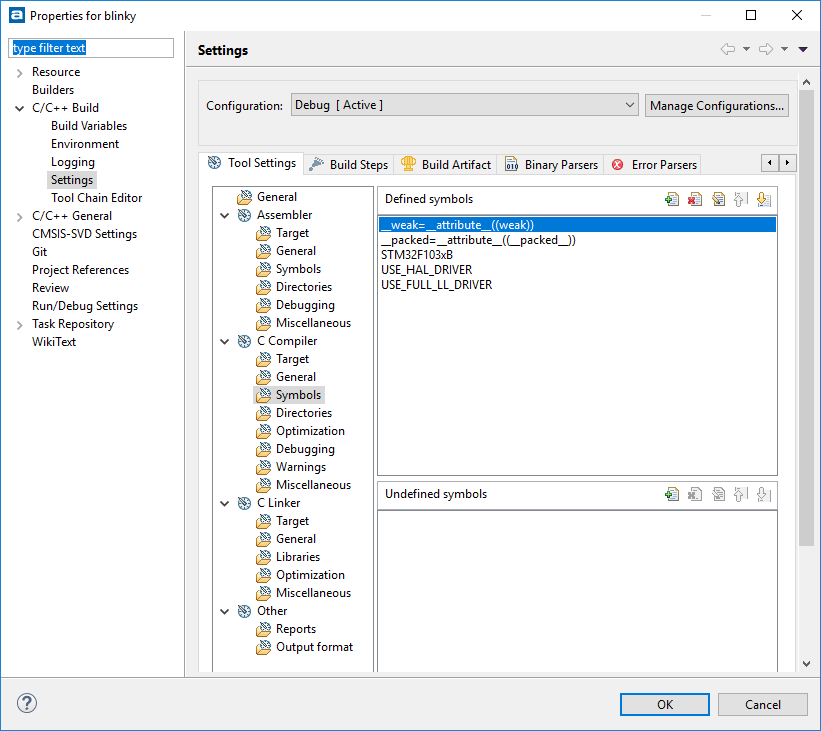
For example, I am currently trying to activate the UART5 for that challenge. I have managed to track down the HAL_drivers for the UART in the initial download and add those into my existing project. Partly comparing a simple UART example I made to see what is required. All the HAL_UART functions are greyed out because HAL_UART_MODULE_ENABLED is not defined. When I look at the simple example I see these are defined in STM32xx_HAL_conf.h but in my example from the STM32xxCube package there doesn't appear to be such a file.


If I manage to find a solution I will post it here - current thinking is to (1) simply define the above and see what happens (2) copy the whole header file from another project and adjust for my current one


Any simple tips, explanation of the basics or links to concise articles would be really appreciated. I really want to crack my understanding of these ARM based boards - I have several now and really want to make something useful with them.


Rod

  • Sign in to reply
  • Cancel

Top Replies

  • avnrdf
    avnrdf over 6 years ago +4
    Rod, I've been using CubeMX + Atollic Studio to program a STM32F103. I'm using the STM32 HAL, and it seems to be working fine for me. First setup CubeMX by downloading the MCU Package: Create a new CubeMX…
  • avnrdf
    avnrdf over 6 years ago in reply to 14rhb +3
    This is what my project looks like: CubeMX generated the hal_conf.h file, and automatically defined the macros. Since you're working with an example project, you could try importing the drivers manually…
  • 14rhb
    14rhb over 6 years ago in reply to kulky64 +3
    I've got 100% UART data now on CN9-pin1, thank you so much kulky64 for all your time taking me through this. Point-by-point: I was looking at CN9-pin2 for the very reason you mention, that is was detailed…
Parents
  • avnrdf
    avnrdf over 6 years ago

    Rod,


    I've been using CubeMX + Atollic Studio to program a STM32F103. I'm using the STM32 HAL, and it seems to be working fine for me.


    First setup CubeMX by downloading the MCU Package:

    image

    Create a new CubeMX project, and enable the peripherals you want (let's go with the GPIO & UART):

    image

    Go to the 'Configuration' tab and configure the settings:

    image

    This is how my project settings look:

    imageimage

    Note that you can select between the 'LL' & 'HAL'. The HAL is easier to work with due to the higher level of abstraction:

    image

    Now click on 'Generate' source code. It should automatically create/update the Atollic TrueStudio Project, add the initialization code (so that you don't need to manually configure the baud rate, and set the GPIOs to the alternate function i.e. UART) & import the required drivers.

    Launch TrueStudio, and you will see something like this:

    image


    If you open up the those functions, you'll see that CubeMX has already implemented the code required to setup the peripheral.


    To transmit you can try adding this after the peripheral initialization:

      char mword [] = "Boot!\n";
      HAL_UART_Transmit(&huart1, &mword, sizeof(mword), 300);


    To toggle the GPIO, try:

    HAL_GPIO_TogglePin(GPIOC,GPIO_PIN_13);
    HAL_Delay(1000);


    Have a look at the documentation for the HAL & LL drivers if you want a list of all the driver functions, how to use them or what they do. For the STM32F1, I use this:

    image


    Regarding the preprocessor macros/symbols,

    TrueStudio > Project > Build Settings > C/C++ Build > Settings > Tool Settings > Symbols (under C Compiler)

    image


    I wouldn't bother with copying files over manually - CubeMX does all of that for you!

    Create a CubeMX project, and add you code between the /*User Code*/ comments. When you want to modify pinmuxing, enable peripherals, or even change peripheral configuration, open CubeMX, make your changes and regenerate the project. CubeMX will not modify anything within the /*User Code*/ braces.


    It's probably easier to start with the CubeMx project, and import whatever code you have rather than the other way around.

    • Cancel
    • Vote Up +4 Vote Down
    • Sign in to reply
    • Cancel
  • 14rhb
    14rhb over 6 years ago in reply to avnrdf

    Hi Avner,


    I wanted to click 'helpful' twice to reflect the amount of great detail you've given me - so thank you.

    CubeMX will not modify anything within the /*User Code*/ braces.

    I wondered how that bit worked following on from koudelad comments, so will remember that as I start to work my own projects from scratch.


    I have managed to do a CubeMX project from scratch, albeit just generating some basic code. The problem I have is that I already have the example from the STM32 board's Cube package, it does 99% of what I want, and now I wish to modify it slightly.


    Rod

    • Cancel
    • Vote Up 0 Vote Down
    • Sign in to reply
    • Cancel
  • avnrdf
    avnrdf over 6 years ago in reply to 14rhb

    This is what my project looks like:

    image

    CubeMX generated the hal_conf.h file, and automatically defined the macros.

    Since you're working with an example project, you could try importing the drivers manually.

    The hal_conf.h file also contains a bunch of other defines, and does a:


    #ifdef HAL_UART_MODULE_ENABLED
     #include "stm32f1xx_hal_uart.h"
    #endif /* HAL_UART_MODULE_ENABLED */


    Try generating a new CubeMX project, and look at how the whole thing is structured. I think that you should be able to copy over files from the CubeMX project to your example, and with a little fixing, it should work.

    • Cancel
    • Vote Up +3 Vote Down
    • Sign in to reply
    • Cancel
  • 14rhb
    14rhb over 6 years ago in reply to avnrdf

    Good advice, thank you again Avner.


    The more I browse around and try stuff the better I'm getting. I have been in the ...hal_conf.h file and enabled the UART (as in photo below) although that definition never seemed to get recognised in the HAL_UART.c and so I changed the #ifdef to #ifndef to get the code to be included....probably a bad approach as there is something obviously not quite right still. I suspect my includes or where the IDE is looking is incorrect although strangely I can trace through from one declaration to the next (so the IDE knows where everything is even if the compiler doesn't).


    I'll likely be giving this a break for now as I think my brain is getting confused - a nice fresh start again tomorrow might help along with all these great comments. A screenshot from my IDE looks like this:

    image


    I have two projects open - the SensorTile example and my own, very basic, UART5.


    Rod

    • Cancel
    • Vote Up 0 Vote Down
    • Sign in to reply
    • Cancel
  • kulky64
    kulky64 over 6 years ago in reply to 14rhb

    Hi, is your basic UART example working? As a starting point try something simple, like sending back every received character. Verify with PuTTY or some other terminal program that it works.

    • Cancel
    • Vote Up 0 Vote Down
    • Sign in to reply
    • Cancel
  • 14rhb
    14rhb over 6 years ago in reply to kulky64

    Hi kulky64, Good point, I compiled the code for reference reading but never actually tried building it or debugging on the SensorTile board. I made a new version in CubeMX (which is a really great tool) and activated both the UART5 and LP_UART. I added some code to output a few bytes on UART5 and LP_UART. I'm seeing bytes on my simple oscilloscope directly from pin 6 of the SensorTile and on CN9-pin2 (having made the SB changes you helpfully suggested). However I wasn't convinced it was actually my bytes (I used the 'U' as it is 0x55 and easy to spot). Commenting out those lines and I could still see data on the CN9-pin2 , which is strange. I'm carrying on looking around. Although I also initialise LP_UART and send bytes to that I cannot see anything on the correct pins of the SensorTile (pins 12 and 13 which are F8 and F9 of the STM32L476JG device). Of course, there is every possibility I have damaged those pins with my clumsy eyesight and shorting pins whilst testing! The data on UART5 also appears whilst single stepping in debug mode, which backs my theory up.


    Anyway, the investigation continues, and although I am now a long way from the actual Sixth Sense Design Challenge I feel I am really learning a lot. I even almost successfully imported the BSP for the SensorTile into my project which didn't seem to be an option from CubeMX (I say almost because it fell over compiling).


    Apart from these issues I've found it enjoyable looking around the CubeMX to see what can get added, selecting the pins, comparing to the datasheets, testing the pins etc. Thanks for all the help and I'll post when I get another breakthrough (the first breakthrough being my simple code actually compiled and downloaded today).


    Rod

    • Cancel
    • Vote Up +2 Vote Down
    • Sign in to reply
    • Cancel
  • kulky64
    kulky64 over 6 years ago in reply to 14rhb

    14rhb  wrote:


    ... I added some code to output a few bytes on UART5 and LP_UART. I'm seeing bytes on my simple oscilloscope directly from pin 6 of the SensorTile and on CN9-pin2 ...

    Whoa. Why do you expecting to see anything on pin 6 of the SensorTile and CN9 pin 2? If you trasmit something from UART5 on SensorTile you should see it on pin 7 of the SensorTile and pin 1 of CN9. So the flow of the signal is like this:

    STM32L476JG (PC12, ball B3, UART5_TX) -> SensorTile (pin 7, signal TXD-USB_DM) -> solder bridge SB20 -> level converter ST2378ETTR -> CN9 pin 1 (signal now named UART_RX because this is from MCU on Nucleo point of view).

    When you are dealing with RXD and TXD nomenclature you should pay attention from standpoint of which device this is taken. Also just to verify: you have not connected any USB cable to USB connector on the Cradle Expansion Board and jumper on J2 header is placed between 1 and 2 (VIN from Nucleo 5V Output). Right?

    • Cancel
    • Vote Up +1 Vote Down
    • Sign in to reply
    • Cancel
  • 14rhb
    14rhb over 6 years ago in reply to kulky64

    image I've got 100%  UART data now on CN9-pin1, thank you so much kulky64 for all your time taking me through this.


    Point-by-point:

    • I was looking at CN9-pin2 for the very reason you mention, that is was detailed as the UART_TX but now I see what you mean about being careful. There was nothing on the CN9-pin 1 at this time.
    • The USB was still connected to my PC and the J2 jumper was incorrectly set to USB.
    • I changed CubeMX back to provide UART5 as asynchronous rather than half-duplex which I changed whilst trying to mend it earlier.
    • A few attempts at building, stopping the existing debug etc (just me getting used to the process still) and wow - the oscilloscope trace went wild...zooming in I can easily see my bytes due to the '0101' nature of the 'U' character.


    Thanks again for all the time you have spent helping me here. What a great way to finish off Sunday image


    Rod

    • Cancel
    • Vote Up +3 Vote Down
    • Sign in to reply
    • Cancel
Reply
  • 14rhb
    14rhb over 6 years ago in reply to kulky64

    image I've got 100%  UART data now on CN9-pin1, thank you so much kulky64 for all your time taking me through this.


    Point-by-point:

    • I was looking at CN9-pin2 for the very reason you mention, that is was detailed as the UART_TX but now I see what you mean about being careful. There was nothing on the CN9-pin 1 at this time.
    • The USB was still connected to my PC and the J2 jumper was incorrectly set to USB.
    • I changed CubeMX back to provide UART5 as asynchronous rather than half-duplex which I changed whilst trying to mend it earlier.
    • A few attempts at building, stopping the existing debug etc (just me getting used to the process still) and wow - the oscilloscope trace went wild...zooming in I can easily see my bytes due to the '0101' nature of the 'U' character.


    Thanks again for all the time you have spent helping me here. What a great way to finish off Sunday image


    Rod

    • Cancel
    • Vote Up +3 Vote Down
    • Sign in to reply
    • Cancel
Children
  • kulky64
    kulky64 over 6 years ago in reply to 14rhb

    Glad it is working. Now you can utilize virtual serial port on ST-LINK and check if you receive characters sent by SensorTile in terminal program on your PC. Connect some female to female jumper cable from ST morpho connector CN10 pin 37 (also connected to CN9 pin 1) to connector CN3 pin RX (provided you already opened SB13). Set baudrate and other parameters in your terminal program to match what you set in firmware on your SensorTile and watch if you receive something in terminal.

    • Cancel
    • Vote Up +2 Vote Down
    • Sign in to reply
    • Cancel
  • 14rhb
    14rhb over 6 years ago in reply to kulky64

    Just like before I read what you said and followed it on the schematics to see if it made sense which it does. A bit of trial-and-error with PuTTY and my SensorTile boards would like to say:

    image

    Rod

    • Cancel
    • Vote Up +3 Vote Down
    • Sign in to reply
    • Cancel
  • kulky64
    kulky64 over 6 years ago in reply to 14rhb

    If you want you can try another direction, connect anothwer wire from CN3 pin TX to CN10 pin 35 (maybe you already done that). You have to be careful now and ensure that the MCU on the Nucleo board does not drive the TX line too (because you have now SB63 shorted) -> potential of conflict here. Modify the firmware on the SensorTile so that it sends back every character received or one character higher or something. Type some characters in terminal a watch if they come back. If you are not sure, maybe don't do this exercise.

    • Cancel
    • Vote Up +2 Vote Down
    • Sign in to reply
    • Cancel
  • 14rhb
    14rhb over 6 years ago in reply to kulky64

    Thank you. I might try this out after the Sixth Sense Challenge has finished, just in case I damage the board - it would be a shame to do that after getting this far !


    Rod

    • Cancel
    • Vote Up 0 Vote Down
    • Sign in to reply
    • Cancel
element14 Community

element14 is the first online community specifically for engineers. Connect with your peers and get expert answers to your questions.

  • Members
  • Learn
  • Technologies
  • Challenges & Projects
  • Products
  • Store
  • About Us
  • Feedback & Support
  • FAQs
  • Terms of Use
  • Privacy Policy
  • Legal and Copyright Notices
  • Sitemap
  • Cookies

An Avnet Company © 2025 Premier Farnell Limited. All Rights Reserved.

Premier Farnell Ltd, registered in England and Wales (no 00876412), registered office: Farnell House, Forge Lane, Leeds LS12 2NE.

ICP 备案号 10220084.

Follow element14

  • X
  • Facebook
  • linkedin
  • YouTube