element14 Community
element14 Community
    Register Log In
  • Site
  • Search
  • Log In Register
  • Community Hub
    Community Hub
    • What's New on element14
    • Feedback and Support
    • Benefits of Membership
    • Personal Blogs
    • Members Area
    • Achievement Levels
  • Learn
    Learn
    • Ask an Expert
    • eBooks
    • element14 presents
    • Learning Center
    • Tech Spotlight
    • STEM Academy
    • Webinars, Training and Events
    • Learning Groups
  • Technologies
    Technologies
    • 3D Printing
    • FPGA
    • Industrial Automation
    • Internet of Things
    • Power & Energy
    • Sensors
    • Technology Groups
  • Challenges & Projects
    Challenges & Projects
    • Design Challenges
    • element14 presents Projects
    • Project14
    • Arduino Projects
    • Raspberry Pi Projects
    • Project Groups
  • Products
    Products
    • Arduino
    • Avnet Boards Community
    • Dev Tools
    • Manufacturers
    • Multicomp Pro
    • Product Groups
    • Raspberry Pi
    • RoadTests & Reviews
  • Store
    Store
    • Visit Your Store
    • Choose another store...
      • Europe
      •  Austria (German)
      •  Belgium (Dutch, French)
      •  Bulgaria (Bulgarian)
      •  Czech Republic (Czech)
      •  Denmark (Danish)
      •  Estonia (Estonian)
      •  Finland (Finnish)
      •  France (French)
      •  Germany (German)
      •  Hungary (Hungarian)
      •  Ireland
      •  Israel
      •  Italy (Italian)
      •  Latvia (Latvian)
      •  
      •  Lithuania (Lithuanian)
      •  Netherlands (Dutch)
      •  Norway (Norwegian)
      •  Poland (Polish)
      •  Portugal (Portuguese)
      •  Romania (Romanian)
      •  Russia (Russian)
      •  Slovakia (Slovak)
      •  Slovenia (Slovenian)
      •  Spain (Spanish)
      •  Sweden (Swedish)
      •  Switzerland(German, French)
      •  Turkey (Turkish)
      •  United Kingdom
      • Asia Pacific
      •  Australia
      •  China
      •  Hong Kong
      •  India
      •  Korea (Korean)
      •  Malaysia
      •  New Zealand
      •  Philippines
      •  Singapore
      •  Taiwan
      •  Thailand (Thai)
      • Americas
      •  Brazil (Portuguese)
      •  Canada
      •  Mexico (Spanish)
      •  United States
      Can't find the country/region you're looking for? Visit our export site or find a local distributor.
  • Translate
  • Profile
  • Settings
Tektronix
  • Products
  • Manufacturers
  • Tektronix
  • More
  • Cancel
Tektronix
Blog Understanding How To Analyze Jitter
  • Blog
  • Forum
  • Documents
  • Events
  • Polls
  • Members
  • Mentions
  • Sub-Groups
  • Tags
  • More
  • Cancel
  • New
Join Tektronix to participate - click to join for free!
  • Share
  • More
  • Cancel
Group Actions
  • Group RSS
  • More
  • Cancel
Engagement
  • Author Author: r.ngugi
  • Date Created: 30 Aug 2024 10:39 AM Date Created
  • Views 1143 views
  • Likes 7 likes
  • Comments 1 comment
  • oscilloscope
  • jitter
  • jitter analysis
Related
Recommended

Understanding How To Analyze Jitter

r.ngugi
r.ngugi
30 Aug 2024

image

Why You Should Care About Jitter

Jitter is a common problem. A quantified misplacement in time of the signal relative to the expected time position, jitter is ultimately a degradation of the key definition of performance of a serial link, which is the bit error ratio. Power distribution networks (PDNs) can cause noise as well as jitter; both can cause transmission errors and increase the bit error ratio of a serial link.

Engineers need to characterize their devices definitely in terms of the bit error ratio. They want to know whether their device is measuring up to the target bit error ratio, whether it has forward error correction, and what is the target bit error ratio they need to reach. The behavior of different elements is very relevant to the total behavior and impairment of a device.

Traditionally, Bit Error Rate Testers (BERTs) were used as instruments to directly measure the bit error ratio, which is the actual measurement target, but those devices are very expensive, and they don't really help people identify the root causes of impairments of the links. As a result, the industry developed alternate approaches using oscilloscopes and advanced custom analysis tools, which are better focused on the causes of error, are more cost-effective and have faster throughput. Bit error requirements have been translated to jitter and noise budgets.

Consider a serial link with a transmitter, channel, and receiver. From the receiver's point of view, we can see that the decision threshold is impaired by the noise in the system, and the time reference is impaired by jitter. By extracting jitter and noise and identifying them clearly in a serial link, we can extrapolate their effects to predict the bit error ratio and understand the performance of the system. Jitter analysis evaluates a waveform in the horizontal dimension based on when the waveform crosses a horizontal reference line, while noise analysis evaluates along a vertical dimension on the basis of crossings of a vertical reference line, typically in the center of the eye; combining jitter and noise analysis provides a better prediction of bit error ratio performance.

Types of Jitter

Jitter is caused by many things, including:

  • Broadband noise density jitter: Wideband noise related to power loss impedance that shows up as voltage in sensitive circuits, creating jitter.
  • Power rail resonance jitter: Impedance resonance, with noise peaks that convert to AM in the power supplier rail of a sensitive circuit.

image

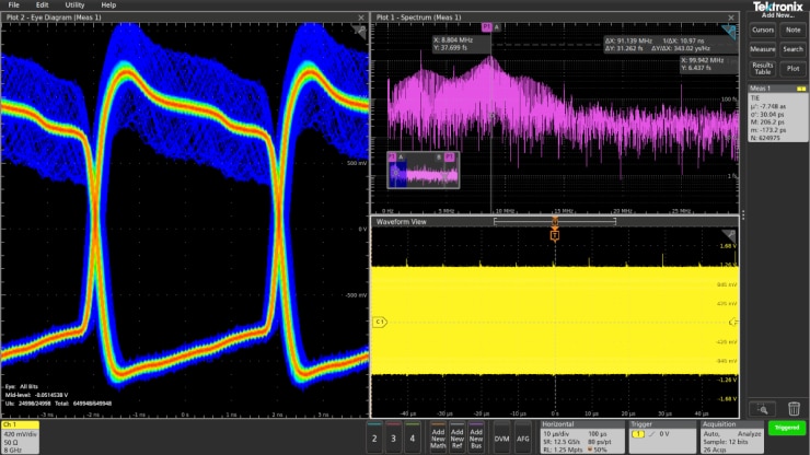
Image 1: Example of Power Rail Resonance Jitter

  • Event-driven jitter: Jitter that occurs because of something else that happened in the system.
  • Modulation-induced jitter: FM or phase modulation that converts to AM on the power supply rail.
  • Thermal noise: Typically a Gaussian distribution, thermal (or intrinsic) noise is unbounded and caused by the random thermal motion of carriers. It’s much like background conversations … random and ever-changing.
  • Injected noise: Jitter from electromagnetic interference (EMI) or crosstalk from neighboring wiring, injected noise is bounded but uncorrelated to the data stream the device is handling. It usually has a fixed, identifiable source, like an oscillator or power supply.

image

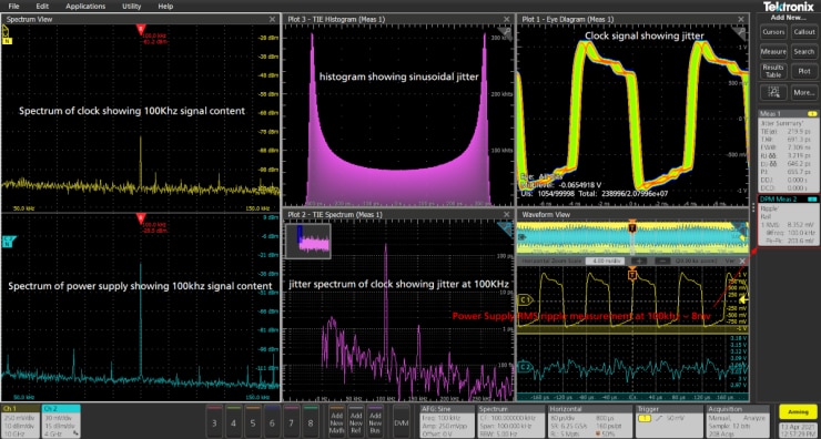
Image 2: Example of Jitter on Clock from Power Supply

  • Transmission losses: Jitter due to bandwidth limitations, skin effect losses, dielectric absorption, dispersion in the optical fiber, or reflections, impedance and mismatches.

How to Analyze Jitter and Noise 

The goal is to predict, using limited acquired data, the behavior of a device at target bit error ratio specifications. The methods are complex, requiring the tester to decompose, reconcile and model noise and jitter. It involves a five-step process:

  1. Acquire statistically relevant data. How to do so depends on whether the oscilloscope in use is a real-time or a sampling instrument.
  2. Break down and separate the various jitter and noise components.


    image

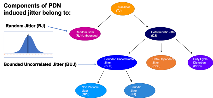
  3. Reconcile the effects of jitter and noise. What is jitter? What is noise? Noise is always jitter, but jitter is not always noise.
  4. Build statistical models that allow for extrapolation of behaviors to higher BER targets.
  5. Perform measurement on the models for Total Jitter as a Specified Bit Error Rate (TJ@BER) and Total Noise at a Specified Bit Error Rare (TN@BER).

The serial data standards of today’s high-speed communications require extensive jitter compliance tests. Learn more about how Tektronix' test instrumentation portfolio enables you to meet design goals and compliance requirements or view our on-demand webinar, Signal and Power Integrity.

This blog first appeared on the Tektronix website. 

  • Sign in to reply
  • battlecoder
    battlecoder 10 months ago

    This is a great summary of the issue of Jitter.  It's a bit unfortunate that scopes with on-board Jitter analysis tools are normally the "highest"-end units, way outside the budget of most people (although arguably, this kind of analysis is mostly required by labs, that can probably afford them)

    Now, I've seen some tools for LabView and similar software packages, but I've not seen a vendor-provided (let's say, Tektronix) software suite that at least allows for that kind of analysis to be performed on a PC connected to one of their scopes capturing data. It should (theoretically) be possible.

    I have to admit, however, that I've not looked that much, but at least from the brands of scopes I own, I'm yet to see something like that.

    I can only hope for a day with this kind of analysis becomes a de-facto feature for even entry or mid-level scopes. As electronics become primarily digital, this could eventually become a "must".

    • Cancel
    • Vote Up 0 Vote Down
    • Sign in to reply
    • More
    • Cancel
element14 Community

element14 is the first online community specifically for engineers. Connect with your peers and get expert answers to your questions.

  • Members
  • Learn
  • Technologies
  • Challenges & Projects
  • Products
  • Store
  • About Us
  • Feedback & Support
  • FAQs
  • Terms of Use
  • Privacy Policy
  • Legal and Copyright Notices
  • Sitemap
  • Cookies

An Avnet Company © 2025 Premier Farnell Limited. All Rights Reserved.

Premier Farnell Ltd, registered in England and Wales (no 00876412), registered office: Farnell House, Forge Lane, Leeds LS12 2NE.

ICP 备案号 10220084.

Follow element14

  • X
  • Facebook
  • linkedin
  • YouTube