
TT Electronics is a global provider of engineered technologies for performance critical applications.
TT Electronics offers one of the industry's most extensive portfolios of sensors and passive components. Explore our product portfolio below.
OPTOELECTRONICS POTENTIOMETERS

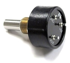


Introduction
Selecting a potentiometer can look straightforward: determine the required resistance, choose a package and shaft, and check the power rating.
For a simple adjustment function, that may be enough. For position feedback, frequent operator adjustment, calibration or operation in a demanding environment, it usually is not. The electrical output of a potentiometer depends on a mechanical contact moving across a resistive element. That makes electrical performance, mechanical design and operating conditions closely linked. Independent linearity, contact resistance variation, rotational life, power dissipation, electrical travel and environmental exposure can all influence whether the component continues to perform as expected over the life of the equipment.
A useful starting point is therefore not the resistance value, but the job the potentiometer is expected to perform.
1. Define the Function and Duty Cycle First
A front-panel control, a production calibration adjustment and a position-feedback sensor may all use a potentiometer, but they place very different demands on it.
An operator control may be adjusted thousands or millions of times and needs appropriate rotational life, torque and mechanical construction. For a calibration function that is set
during production and rarely adjusted afterwards, stability and adjustment resolution may matter more than high cycle life. A position-feedback device introduces another set of priorities,
including independent linearity, output smoothness and repeatability.
The differences can be significant even within one manufacturer’s portfolio.
BI Technologies P260/P261 panel potentiometers, for example, are 12.7 mm rotary conductive-plastic devices available in configurations with up to six gangs. The family covers resistance
values from 500 Ω to 1 MΩ and includes sealed/dust-proof construction, linear and audio tapers, switch, detent and wire-lead
options. Selected configurations are specified for a one-million-cycle life.
For precision position sensing, the requirements can be considerably different. The BI Technologies 6180 Series is a single-turn conductive-plastic precision potentiometer with
resistance values from 1 kΩ to 100 kΩ. Depending on model and configuration, minimum cycle-life ratings extend to a minimum of
five million.
The intended function and expected number of operations should therefore be established before comparing nominal resistance values.
2. Match the Resistive Values to the Requirement
The resistive element has a direct influence on electrical behaviour, power capability, resolution and operating life.
Wirewound potentiometers use resistance wire wound around an insulating former. They are well established in precision measurement and control applications where stability, power handling and tight linearity are important. One trade-off is that the discrete turns of resistance wire inherently limit resolution compared with a continuous resistive track.
As an example, BI Technologies 7280 Series is a 10-turn wirewound precision potentiometer offering resistance values from 100 Ω to 100 kΩ, a 2 W power rating and ±0.25% standard independent linearity. Depending on the model, minimum cycle-life ratings extend to 300,000 rotations.
Conductive-plastic potentiometers use a continuous resistive element and are particularly useful where smooth output and high operational life are required. The 6180 Series, for comparison, is rated at 1 W at 70°C, provides ±1% standard independent linearity with ±0.5% listed as the minimum practical value, and specifies output smoothness of 0.1% maximum.
Carbon elements continue to provide an economical solution for less demanding adjustment and control functions, particularly where precision and very high cycle life are not primary design requirements.
For PCB calibration, cermet is another important option. The 67 Series trimmers, for example, uses cermet elements and includes 20-turn configurations for fine adjustments. Selected versions are sealed for compatibility with aqueous PCB-cleaning processes.
The choice is therefore not a question of one technology being better than another. It is a trade-off between the electrical, mechanical and cost requirements of the application
3. Look Beyond Resistance Value and Tolerance
Nominal resistance and tolerance are necessary specifications, but they do not describe how accurately shaft position will be represented at the wiper.
For a potentiometer used as a voltage divider or position sensor, independent linearity is often more directly related to positional accuracy. It describes how closely the actual output follows a specified straight-line relationship over the electrical travel.
Consider two BI Technologies precision products:
The single-turn wirewound 5100 Series has a standard independent linearity of ±0.5%, with ±0.25% listed as the minimum practical value. The 10-turn wirewound 7280 Series specifies ±0.25% standard independent linearity.
By contrast, the conductive-plastic 6180 Series specifies ±1% standard independent linearity, with ±0.5% available as a minimum practical value. It also specifies 0.1% maximum output smoothness.
Those differences illustrate why the selection cannot be based on resistance alone. The designer should consider which error mechanisms matter to the circuit and how the potentiometer is being used.
Other parameters worth checking include:
Loading should also be considered. A potentiometer used as a voltage divider produces its most predictable transfer characteristic when the load connected to the wiper is high relative to the potentiometer resistance. A low-impedance load changes the effective divider ratio and introduces non-linearity even if the potentiometer itself has excellent independent linearity.
The component specification and the surrounding circuit therefore have to be considered together.
4. Match Mechanical Life to the Actual Duty Cycle
Cycle-life figures only become useful when with the expected duty cycle of the application.
Suppose an operator control is moved 500 times per working day. At 250 working days per year, that represents 125,000 cycles annually. A product intended to remain in service for eight years could therefore approach one million operations.
A calibration control adjusted during manufacture may accumulate only a fraction of that number.
BI Technologies portfolio illustrates the range. The 7280 wirewound precision family includes models with minimum life ratings to one million rotations. Standard 6180 conductive-plastic configurations are available with five-million-cycle ratings. P260/P261 panel-control configurations are available with ratings up to one million cycles.
These figures should not be compared in isolation because the products serve different purposes and their ratings are based on specified test conditions. They do, however, demonstrate why expected movement should be quantified early.
Specifying far more endurance than the application requires can add unnecessary cost. Specifying too little may turn an inexpensive component into a field-reliability problem.
5. Design for the Operating Environment
A potentiometer can meet every required electrical parameter at room temperature and still be unsuitable for the equipment in which it is installed.
Temperature affects both power capability and electrical performance. Power ratings are therefore normally accompanied by a derating curve rather than remaining constant across the full operating-temperature range.
For example, the BI Technologies 6180 Series is rated at 1 W at 70°C and derates to zero power at 125°C. A designer cannot assume that the 1 W headline rating applies at every operating temperature.
Shock and vibration can also matter when the potentiometer is mechanically coupled to a moving assembly. The BI Technologies 5100 Series, for example, is specified for 100 g, 6 ms sawtooth shock and 10 g vibration from 10 to 500 Hz. Its environmental data also includes temperature cycling and humidity testing, while rotational load life is specified as 500,000 shaft revolutions plus 900 hours at rated power at 40°C.
Contamination presents a different problem. Dust or moisture reaching the resistive track and wiper can affect electrical contact and long-term performance, making sealing and housing construction important selection criteria.
Instead of treating environmental specifications as a final qualification check, they should be part of initial component selection alongside the electrical requirements.
6. Treat Mechanical Integration as Part of the Electrical Design
A potentiometer may satisfy the electrical requirements and still create integration problems if the mechanical interface is considered too late.
Shaft diameter and length, bushing dimensions, mounting method, rotational travel, available panel depth and termination style all constrain the design.
Electrical and mechanical travel also need to be distinguished. The full physical rotation of the shaft is not necessarily the portion over which the specified electrical transfer characteristic applies. The P260/P261 Series, for example, specifies a nominal electrical travel of 265°, while the 6180 precision series specifies nominal actual electrical travel of 340° in its standard configuration.
The required taper is another application-dependent choice. A linear taper is appropriate where resistance or output voltage should vary approximately in proportion to position. Other response characteristics are useful where the required output is intentionally non-linear. The P260/P261 family, for example, is offered with both linear and audio taper options.
Mechanical configuration can also affect assembly complexity. The same P260/P261 platform supports PCB pins, solder lugs, wire leads, ribbon cable, detents, rotary switches and multiple-gang configurations. Selecting the appropriate interface at component level can remove the need for additional mechanical or wiring components elsewhere in the assembly.
Where a standard configuration does not fit, shaft geometry, electrical characteristics, terminations and other parameters may also be candidates for customisation.
A Practical Selection Check
Before releasing a potentiometer into a design, it is useful to be able to answer six questions:
|
Design Question |
Parameter to Check |
|
What is the potentiometer doing? |
Adjustment, calibration or position feedback. |
|
How accurately must position or adjustment be represented? |
Independent linearity, output smoothness/CRV, repeatability, electrical travel. |
|
How often will it move? |
Rated cycle life, torque and duty cycle. |
|
What electrical stress will it see? |
Resistance, power rating, maximum voltage and derating. |
|
Where will it operate? |
Temperature, sealing, shock, vibration and contamination |
|
How will it fit into the equipment? |
Shaft, bushing, mounting, terminations, taper, gangs and available space |
These questions narrow the available choices much more effectively than resistance value alone.
Bringing the Design Together
There is no single specification that determines whether a potentiometer is right for an application. A conductive-plastic device is not automatically preferable to a wirewound device, just as tighter resistance tolerance does not automatically produce more accurate position feedback.
The correct choice depends on what the component is being asked to do.
BI Technologies portfolio includes panel and precision potentiometers as well as trimmers across conductive-plastic, wirewound, carbon and cermet technologies. The range covers applications from operator adjustment and PCB calibration to precision position feedback, with multiple mechanical configurations and custom options available for OEM designs.
When specifying a potentiometer, begin with function, accuracy, duty cycle and operating environment. Once those requirements are defined, resistance value becomes one part of a much clearer engineering decision.
Explore the TT Electronics BI Technologies potentiometer portfolio to compare product options and technical data, or discuss the electrical and mechanical requirements of your application with a Newark, Farnell or element14 representative.
Contributing Authors:
Adam Royles, Bryan Snider, Avery Harrel, Mario Mejorada & William Walsh
Precision Resistors, Potentiometers & Trimmers
Industrial automation and robotics applications require components that deliver precision, reliability and long-term performance in demanding operating environments. Bringing together the trusted Welwyn, IRC and BI Technologies brands, TT Electronics' passive components portfolio provides precision resistors, current sensing solutions, potentiometers, trimmers and encoders engineered to help designers reduce risk, improve system performance and enable reliable operation.

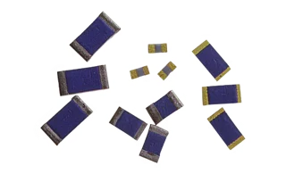
Designed for high-voltage monitoring, feedback and control circuits, Welwyn high-voltage chip resistors offer continuous working voltages up to 3 kV (4 kV overload) and resistance values up to 1 GΩ.
ACCESS DATASHEETS
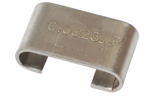
IRC current sense resistors deliver accurate current measurement for motor drives, actuators and servo systems, with resistance values down to 0.2 mΩ and excellent pulse and surge tolerance.
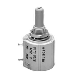
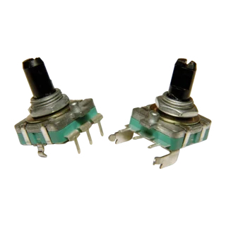
BI Technologies servo mount potentiometers provide precise position sensing and feedback for servo systems and motion control applications, with servo mount configurations and independent linearity to ±0.25%.
BI Technologies encoders deliver reliable rotational position feedback for servo systems, motor control, robotics and industrial automation, using contacting incremental encoding with resolutions of up to 24 PPR.
Selecting resistors for aerospace and defence electronics often includes reviewing the applicable qualification requirements at an early stage. For component engineers, however, that is rarely where the evaluation ends.
Qualification reports provide the evidence that a resistor design has successfully completed the recognised electrical, mechanical and environmental testing. Qualification evidence provides an important assessment of the design and manufacturing process against defined requirements. Engineers may still need to examine ongoing process controls, lot acceptance, change management and application-specific performance when assessing long-term programme suitability.
As platform lifecycles continue to increase and supply chains evolve, engineers are increasingly evaluating not only whether a resistor has been qualified, but also how it is manufactured, how it performs under application-specific conditions and how effectively the supplier can support the programme over the long term.
Qualification demonstrates capability. Ongoing production demonstrates repeatability.
What Happens After Qualification?
Standards such as MIL-PRF-55342, IEC 60115 and ESCC are fundamental to component selection, providing recognised methods for evaluating environmental endurance, mechanical integrity and electrical stability. Typical qualification programmes include load-life endurance, temperature cycling, moisture resistance, vibration, mechanical shock and short-time overload. Key electrical parameters such as resistance and temperature coefficient of resistance (TCR) are verified before and after testing.
For component engineers, these results establish confidence that the resistor design is suitable for its intended application. A key next step is determining whether that level of performance can be consistently reproduced throughout production.
Material selection, substrate quality, thick-film deposition, firing profiles, laser trimming and passivation all influence long-term electrical stability. Equally important are the manufacturing controls behind those processes. Statistical process control (SPC), lot traceability and disciplined engineering change management help ensure production devices continue to perform consistently with the original qualified design. At TT Electronics, more than 40 years of manufacturing experience, supported by millions of component-hours of load-life testing, provides valuable engineering evidence to support long-term reliability assessments and the FIT estimates used during system reliability modelling.
For programmes expected to remain in service for twenty years or more, this depth of manufacturing knowledge is every bit as important as successful qualification.
The Application Matters
Qualification testing evaluates components under a defined set of controlled stresses. Operational environments are rarely so predictable.
A resistor specified for an aircraft flight control computer is exposed to different electrical loading and environmental conditions than one used in a radar power supply, electronic warfare system or satellite communications subsystem. Understanding those conditions helps determine which qualification data deserves the closest scrutiny.
Beyond the qualification report, engineers should consider:
Taken together, these considerations help engineers interpret qualification data in the context of the intended operating environment.
Completing the Engineering Assessment
Completing the engineering assessment means understanding not only how a resistor performed during qualification, but how consistently that performance can be maintained throughout the life of the programme. Controlled manufacturing processes, disciplined engineering change management, production traceability and long-term product support all contribute to reducing both technical and supply chain risk.
Considering these factors alongside recognised qualification data provides a more complete picture of resistor suitability for demanding aerospace and defence applications.
Applying These Principles
These broader considerations are also relevant when evaluating the TT Electronics Welwyn CR Series of thick-film chip resistors.
Manufactured in Bedlington, United Kingdom, the CR Series uses established thick-film technology and is available across multiple package sizes, resistance values and tolerance options. The range is approved to applicable EN 140401 and CECC 40401 specifications and supports analogue, control, power-management and signal-conditioning functions in aerospace, defence and other long-life electronic applications.
Electrical ratings and qualification status remain central to the selection process, but they should be considered alongside the intended operating conditions and the manufacturing and programme controls available for the selected part. Depending on the application, these may include lot traceability, configuration control, change notification and continued product support.
Qualification therefore provides an important foundation for resistor selection. Combining that evidence with application-specific analysis and an understanding of the supplier’s manufacturing and lifecycle controls helps engineers make more complete component decisions for long-term programmes.
Woking, UK - 27, May 2026 - TT Electronics, a global provider of mission-critical power and sensing technology, has been selected to supply Hallogic® Hall-effect sensors for integration into fan assemblies on NASA’s Dragonfly rotorcraft mission. The sensors support a spacecraft subsystem where reliability and consistency are essential across the programme lifecycle.
Hallogic® Hall-effect devices, part of the Optek technology portfolio, are designed for non-contact motion sensing and switching, with variants processed and screened for military and space-grade applications where consistency and reliability are deisgn priorities.
Hallogic® OMH3075S is a high-reliability Hall-effect sensor in the Optek portfolio, designed for non-contact switching and operation across a broad range of supply voltages. The device is specified for operation from -55 °C to +150°C, supporting applications that require reliable switching across wide temperature ranges, and is suitable for military and space applications. For applications requiring enhanced screening, B and S versions are processed and screen to MIL-STD-883, with ESD Class 3B per the same standard.
Dragonfly is a rotorcraft lander mission to Saturn's largest moon, Titan, that is designed to conduct science across multiple locations, sampling surface materials to measure their detailed compositions, and observing geology and meteorology. The Johns Hopkins Applied Physics Laboratory (APL) manages the Dragonfly mission for NASA and is building the rotorcraft, which is scheduled to launch in 2028 and reach Titan in 2034.
"Dragonfly is a mission that demands exceptional reliability and consistency, and we’re proud that the Hallogic OMH3075S has been selected for this application,” said Klaus Zwerschina, VP Components, TT Electronics. “We work closely with customers to de-risk performance-critical designs, supporting programmes that value engineering continuity and a disciplined supply approach from design-in through production, for long service life."
About TT Electronics
TT Electronics is a global provider of engineered electronics for performance-critical applications. The company designs and manufactures solutions that enable a safer, healthier and more sustainable world. Serving key markets including healthcare, aerospace and defence, and industrial, TT Electronics partners with customers to deliver highly reliable solutions where failure is not an option.
Visit www.ttelectronics.com to learn more.
This TT Electronics white paper gives power system architects a practical framework for selecting, calculating, and maintaining optical isolation components designed to last 25 years in demanding grid environments.
Optical Isolation Fundamentals
How galvanic isolation has evolved into a critical performance enabler, including a breakdown of optical coupling mechanics and a comparison of five photodetector types mapped to their industrial applications.
CTR Calculations & Worst-Case Design
How to calculate the Current Transfer Ratio under real operating conditions — with a worked example showing how a nominal 200% CTR device can degrade to 129.2% in the field.
Reliability & LED Aging Mechanics
The Black Formula for predicting long-term CTR degradation, the Five Pillars of Optocoupler Longevity, and how to design for the 2σ worst-case population over a 25-year service life.
Advanced Applications & Compliance
SiC/GaN wide-bandgap driver requirements, integrated smart gate driver comparisons, and a plain-language guide to IEC 60747-5-5, partial discharge testing, and insulation standards.
In the landscape of industrial automation, the debate between maintaining fixed legacy systems and migrating to adaptable optical sensors is not just about technology; it is about operational philosophy. For decades, fixed optical systems—standard logic photocells, basic LED emitters, and fixed-gain optoisolators—have been the backbone of manufacturing. They are reliable, understood, and inexpensive.
However, the shift toward Industry 4.0 has exposed the limitations of these rigid systems. Engineers are now tasked with integrating components that can self-calibrate, communicate status, and adapt to environmental degradation. This article provides a transparent comparison between fixed legacy systems and modern adaptable optical sensors, covering Fibre Optics, Optoisolators, Photologic assemblies, and VCSEL technologies.
A fixed system operates on binary logic or set parameters defined at the hardware level. Once installed, its behaviour is static. For example, a standard infrared emitter paired with a phototransistor will trigger a signal when a light beam is broken. If dust accumulates on the lens, the signal degrades until the system fails. To fix it, a technician must physically clean the sensor or adjust a potentiometer.
Adaptable sensors utilise intelligent circuitry and superior materials (like VCSELs) to adjust to their environment. A programmable Photologic sensor, for instance, might dynamically adjust its hysteresis threshold to account for signal drift caused by temperature changes or debris. These systems prioritise data continuity and predictive maintenance over simple binary switching.
We must acknowledge why legacy systems remain prevalent. They are not without merit.
Lower Upfront BOM Cost – A standard fixed-gain optoisolator or a simple LED-based interrupter is significantly cheaper than a programmable alternative.
Simplicity of Replacement – If a fixed sensor fails, you pull it out and plug in an identical part. There is no firmware to update and no calibration software to run.
Zero Latency – Purely analogue fixed systems often have faster response times than smart sensors that require processing cycles to interpret data.
Legacy systems rely on standard LEDs. While functional, they suffer from beam divergence and lower power efficiency. Adaptable systems utilise Vertical-Cavity Surface-Emitting Lasers (VCSELs). VCSELs offer a narrow, coherent beam that requires less power and provides higher accuracy for position sensing. In adaptable systems, the VCSEL current can be modulated dynamically to maintain constant output power as the component ages.
A fixed system usually employs a discrete photodiode and a separate amplifier circuit. Adaptable Photologic sensors integrate the sensor, amplifier, and logic gate into a single package. The benefit is not just space; it is consistency. These adaptable units often feature internal voltage regulation and temperature compensation that fixed discrete circuits lack.
In high-EMI environments, copper is a liability. While legacy systems try to shield copper, adaptable systems switch to fibre optics. Modern industrial fibre optic links are adaptable because they provide complete electrical isolation and can be routed through hazardous areas where electrical sparks are prohibited. They are immune to the electromagnetic interference that plagues fixed copper legacy systems.
Engineers should consider migrating to adaptable sensors if:
Environmental variation is high – Varying light levels, dust, or temperature swings require sensors that can auto-calibrate.
Downtime is expensive – If stopping a line to wipe a sensor lens costs thousands of pounds, an adaptable sensor that compensates for occlusion is worth the investment.
Precision is critical – If you are moving from simple object detection to precise position sensing, VCSEL-based adaptable systems are required.
Fixed legacy systems are not obsolete, but they are becoming niche. For simple, cost-constrained applications where downtime is manageable, they remain a valid choice. However, for industrial engineers building systems for longevity, reliability, and Industry 4.0 integration, adaptable optical sensors offer a superior return on investment despite the higher upfront cost. By eliminating manual calibration and reducing failure points related to environmental stress, adaptable sensors future-proof manufacturing lines.
Written by TT Electronics


