element14 Community
element14 Community
    Register Log In
  • Site
  • Search
  • Log In Register
  • Community Hub
    Community Hub
    • What's New on element14
    • Feedback and Support
    • Benefits of Membership
    • Personal Blogs
    • Members Area
    • Achievement Levels
  • Learn
    Learn
    • Ask an Expert
    • eBooks
    • element14 presents
    • Learning Center
    • Tech Spotlight
    • STEM Academy
    • Webinars, Training and Events
    • Learning Groups
  • Technologies
    Technologies
    • 3D Printing
    • FPGA
    • Industrial Automation
    • Internet of Things
    • Power & Energy
    • Sensors
    • Technology Groups
  • Challenges & Projects
    Challenges & Projects
    • Design Challenges
    • element14 presents Projects
    • Project14
    • Arduino Projects
    • Raspberry Pi Projects
    • Project Groups
  • Products
    Products
    • Arduino
    • Avnet Boards Community
    • Dev Tools
    • Manufacturers
    • Multicomp Pro
    • Product Groups
    • Raspberry Pi
    • RoadTests & Reviews
  • Store
    Store
    • Visit Your Store
    • Choose another store...
      • Europe
      •  Austria (German)
      •  Belgium (Dutch, French)
      •  Bulgaria (Bulgarian)
      •  Czech Republic (Czech)
      •  Denmark (Danish)
      •  Estonia (Estonian)
      •  Finland (Finnish)
      •  France (French)
      •  Germany (German)
      •  Hungary (Hungarian)
      •  Ireland
      •  Israel
      •  Italy (Italian)
      •  Latvia (Latvian)
      •  
      •  Lithuania (Lithuanian)
      •  Netherlands (Dutch)
      •  Norway (Norwegian)
      •  Poland (Polish)
      •  Portugal (Portuguese)
      •  Romania (Romanian)
      •  Russia (Russian)
      •  Slovakia (Slovak)
      •  Slovenia (Slovenian)
      •  Spain (Spanish)
      •  Sweden (Swedish)
      •  Switzerland(German, French)
      •  Turkey (Turkish)
      •  United Kingdom
      • Asia Pacific
      •  Australia
      •  China
      •  Hong Kong
      •  India
      •  Korea (Korean)
      •  Malaysia
      •  New Zealand
      •  Philippines
      •  Singapore
      •  Taiwan
      •  Thailand (Thai)
      • Americas
      •  Brazil (Portuguese)
      •  Canada
      •  Mexico (Spanish)
      •  United States
      Can't find the country/region you're looking for? Visit our export site or find a local distributor.
  • Translate
  • Profile
  • Settings
Würth Elektronik
  • Products
  • Manufacturers
  • Würth Elektronik
  • More
  • Cancel
Würth Elektronik
Documents The forward converter
  • Blog
  • Forum
  • Documents
  • Events
  • Polls
  • Files
  • Members
  • Mentions
  • Sub-Groups
  • Tags
  • More
  • Cancel
  • New
Join Würth Elektronik to participate - click to join for free!
Actions
  • Share
  • More
  • Cancel
Engagement
  • Author Author: sleuz
  • Date Created: 26 Nov 2012 1:12 PM Date Created
  • Last Updated Last Updated: 16 Nov 2015 1:02 PM
  • Views 1577 views
  • Likes 1 like
  • Comments 1 comment
Related
Recommended

The forward converter

The Forward Converter

Basic Construction and Function

image

Figure 3.179 shows the basic construction of a forward converter. Whereas the energy is temporarily stored with the flyback converter before it is transferred to the secondary side, in the forward converter, energy is transferred directly between the primary and secondary sides.


image

Fig. 3.179: Circuit diagram of a forward converter


As an aid for understanding, the individual switching states in the steady state system are examined. With the switch T1 closed, there is the same polarity at both dots of the transformer circuit diagram so that the diode D2 is conducting. In accordance with the function of the transformer (Chapter I/1.9) the current transformed from the secondary side flows on the primary side and the linearly increasing magnetizing current.


The transformed input voltage is applied to the secondary winding. This serves to charge the choke. A linearly increasing current flows through the choke and the load.

If the switch T1 is now opened, the current cannot continue to flow on the primary side. The polarity in the magnetic components reverses so that D2 is blocked on the secondary side. The choke L1 now transfers the stored energy to the load (or the output capacitor) via D3. The current through the choke again decreases linearly.


The core of the transformer has been magnetized by the magnetization current. The remanence of the core material would cause the core to saturate within a few switching cycles. So it has to be demagnetized after each switching period. Various techniques have been used for this purpose. The simplest option is presented in Figure 3.179. During the shutdown phase the magnetizing current is fed back via diode D1 through the auxiliary winding. The number of turns used for the auxiliary winding is usually the same as that used for the primary winding. This means that the same time is required for demagnetization as for magnetization. The converter can therefore be driven at a maximum duty cycle of 50%.


Further possibilities for demagnetization are presented by the forward converter with two switches (two-switch forward) (Figure 3.180) and the forward converter with active clamping (active-clamp forward) (Figure 3.181). In the case of the two-switch forward, the core is demagnetized via both diodes so that no auxiliary winding is required. For the active-clamp forward, the capacitor on the transformer generates a higher negative voltage, so that the demagnetization is achieved in a shorter time. This means that duty cycles higher than 50% are possible.


image

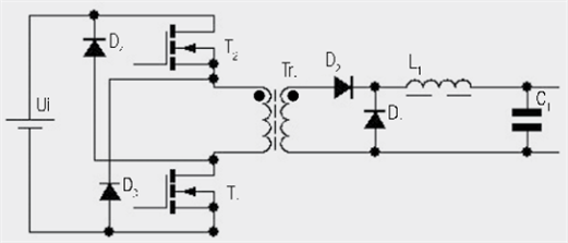
Fig. 3.180: Circuit diagram of a 2-switch forward converter


image

Fig. 3.181: Circuit diagram of a forward converter with active clamping


Additional means of demagnetization are presented by Severns (2000).


Transformer design and defining inductance


As previously mentioned, the forward converter behaves like a step-down converter with pre-switched voltage transformation. The following relationship is therefore given between the turns ratio and the duty cycle:


image

The number of primary turns can be defined for a particular core with the main transformer formula:

image

The effective currents through the transformer are given by:

image

image

This allows the wire thickness for the windings and the copper losses to be determined. Another auxiliary winding may have to be fitted depending of the demagnetization circuit. As it is only the magnetizing current that flows through it here, a relatively fine wire is sufficient. The same approach is taken towards dimensioning the output choke as with the step-down converter. The same relationship exists between the ripple, frequency and inductance:

image

The effective current through the choke is equal to the output current. The peak value is equivalent to the output current plus half the ripple current:

image

Ieff,L = effective current through the choke


image

A standard inductance can now be selected with these data.


-Application Notes & Technical Reports-
-follow us on element14-

  • help
  • directory
  • basic_function
  • basic_construction
  • forward_converter
  • active_clamping
  • explanation
  • advice
  • Share
  • History
  • More
  • Cancel
  • Sign in to reply
  • volly
    volly over 10 years ago

    Highly informative. Welcome more postings like this one. Thanks!image

    • Cancel
    • Vote Up 0 Vote Down
    • Sign in to reply
    • More
    • Cancel
element14 Community

element14 is the first online community specifically for engineers. Connect with your peers and get expert answers to your questions.

  • Members
  • Learn
  • Technologies
  • Challenges & Projects
  • Products
  • Store
  • About Us
  • Feedback & Support
  • FAQs
  • Terms of Use
  • Privacy Policy
  • Legal and Copyright Notices
  • Sitemap
  • Cookies

An Avnet Company © 2025 Premier Farnell Limited. All Rights Reserved.

Premier Farnell Ltd, registered in England and Wales (no 00876412), registered office: Farnell House, Forge Lane, Leeds LS12 2NE.

ICP 备案号 10220084.

Follow element14

  • X
  • Facebook
  • linkedin
  • YouTube