
Power Inductors 8 Design Tips

A practical guide for the selection of power inductors for DC/DC converters
Switching regulators are becoming increasingly important thanks to their high efficiencies. The trend is towards regulators with output voltages lower than 1 V, load currents up to 60 A and switching frequencies up to 8 MHz. At the same time, users demand the smallest possible types. Switching regulator design is supported by specialised software, for example from Würth Elektronik (Component Selector), Texas Instruments (Switcher Pro for TPS60xxx, TPS40xxx and TPS54xxx), Exar (Power Lab), National Semiconductor (WEBENCH) or Linear Technology (Switcher CAD/LTspice IV). The relevant SMD power inductor design kits from Würth Elektronik offer quick access to a range of components for the construction of in-house prototypes or for optimisation. But what has to be taken into account when using power inductors?
Switching frequency
The switching frequency of typical converter ICs on the market is in the range 100 kHz to 2MHz. First generation regulators operated in the range 30 kHz to 55 kHz. This leads to the following recommendations:
DESIGN TIP 1: Suitable core materials
Switching frequency < 100 kHz: Iron powder, ferrite, Superflux, WE-PERM
Switching frequency 100-1000 kHz: Ferrite, Superflux, WE-PERM
Switching frequency > 1000 kHz: Ferrite, WE-PERM
Inductance value
If there is no application note or software available, inductance can be calculated using the following rule-of-thumb formula:
Step-down regulator: L=(Uinmax−Uout)×(Uout+UD)(Uinmax+UD)×0.3×Iout׃
Step-up regulator: L=(Uout+UD−Uinmin)×U2in2×0.2×Iout×(Uout+UD)2׃
with the ripple current factors 0.2 to 0.4 (selected as 0.2 and 0.3 in this example). Iout is the operating current of the circuit to be supplied, Uout the output voltage and Uin the input voltage, f is the switching frequency of the regulator IC. Standard values for inductance L can be selected on the basis of the calculated value. If, for example, the value 37.36 μH is obtained as the result – you would select the standard values 33 μH, 39 μH and possibly also 47 μH for testing.
DESIGN TIP 2
-> higher inductance – smaller ripple current
-> lower inductance – higher ripple current
The ripple current is essential in determining the core losses. Besides the switching frequency, it is therefore an important parameter for minimising the power loss of the power inductor
Inductor current ratings
The current load for power inductors can be calculated very accurately in terms of DC current load and ripple current load (core losses) using the manufacturers’ simulation software. The following approach can be chosen as a rough calculation:
Step-down regulator:
Nominal current of the inductor: IN=Iout
Maximum coil current: Imax=1.5xIN
Step-up regulator:
Nominal current of the inductor: IN=(UoutUin )×Iout
Maximum coil current: Imax=2×IN
DESIGN TIP 3:
Please observe the definitions for the data sheet specifications. The nominal current for power inductors is usually linked to the specified self-heating with DC current – here self-heating of +40°C is common at the nominal current. According to semiconductor manufacturers‘ recommendations, the saturation current is the point at which the inductance value has fallen by 10%. Unfortunately, this is not a standard value for power inductor data sheet specifications and often leads to misinterpretation among users.
DC resistance
Once the required values for inductance L and inductor currents are calculated, you select a power inductor with the minimum possible DC resistance. Here the demands are often counteractive:
Small size, high energy storage density and low DC resistance.
Using suitable winding methods and new series, such as the Würth Elektronik WE-HCI and WE-PDF flat-wire inductors, this ideal case is very close to realisation. The data sheet definition must also be observed here: Is the DC resistance specified as a typical value or as the max. value required for calculating the circuit under worst case conditions?
DESIGN TIP 4: DC resistance with the same size
-> higher inductance – higher DC resistance
-> lower inductance – lower DC resistance
-> same inductance for a shielded inductor – lower DC resistance
The DC resistance is essential in determining the wire heating losses; this is another important parameter for minimising the power loss of the power inductor.
Type and EMC
Magnetic shielded power inductors like WE-PD, WE-TPC, WE-DD or WE-HCI are recom mended for EMC-critical applications. The shielding prevents uncontrolled magnetic coupling of the windings with neighbouring conductor tracks or components.
DESIGN TIP 5:
Use a magnetically shielded power inductor if at all possible. Do not route any conductor tracks under the component and do not place any circuit boards directly above the component, as this could give rise to coupling via the air gap remaining.
Unshielded power inductors like WE-PD2 can be used for uncritical applications or for low power circuits. Many packaging series can even be changed from shielded to unshielded versions while maintaining solder pad compatibility.
DESIGN TIP 6:
Advantage of magnetically shielded inductors of the same type:
-> higher AL value, therefore lower DC resistances for the same inductance = lower wire losses.
Disadvantage of magnetically shielded inductors of the same type:
-> slightly increased core losses due to a larger core volume. Given correct dimensioning the core losses remain low.
Output L-C filter
An L-C filter at the DC converter output is recommended if a low noise output voltage is required. The components can be selected as follows [1]:
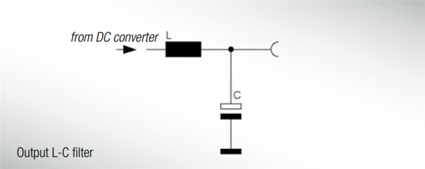
DESIGN TIP 7:
-> Select cut-off frequency at 1/10 of the switching regulator frequency
-> Select output capacitor (e.g. 22 µF)
-> Calculate inductance
L=1(2×π׃ )×C
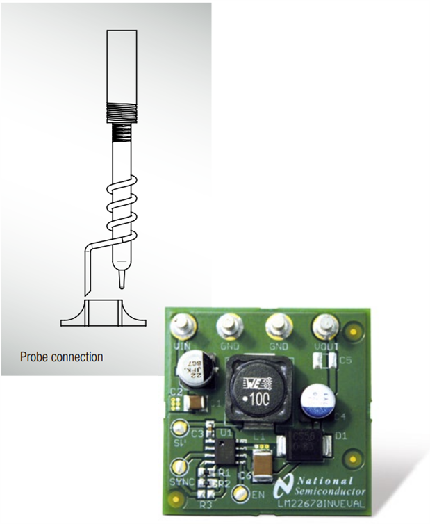
DESIGN TIP 8: Ripple measurements
To properly measure ripple on either input or output of a switching regulator, a proper ring in Tipp measurement is required. Standard oscilloscope probes come with a grounding clip, or a long wire with an alligator clip. Unfortunately, for high frequency measurements, this ground clip can pick-up high frequency noise and erroneously inject it into the measured output ripple.
The standard evaluation board accommodates a home made version by providing probe points for both the input and output supplies and their respective grounds. This requires the removing of the oscilloscope probe sheath and ground clip from a standard oscilloscope probe and wrapping a non-shielded bus wire around the oscilloscope probe. If there does not happen to be any non shielded bus wire immediately available, the leads from axial resistors will work. By maintaining the shortest possible ground lengths on the oscilloscope probe, true ripple measurements can be obtained.
Summary
The power inductor selection steps described are based on the design tips given in this article and are linked to the data sheet specifications. Not only the relevant design software from the semiconductor manufacturer serves to reduce development times. With the software Component Selector you get a tool which identifies very quick the right inductance for a buck or a boost converter. As a matter of course power inductors from Würth Elektronik are also listed in the leading semiconductor manufacturers‘ software solutions and hence they are immediately available for inclusion in the simulations. Correspondingly assembled design kits help optimise prototypes. Magnetically shielded power inductors should be deployed for EMC-critical applications.
References:
[1] Schramm, C.; DC-Wandler: Ausgangsspannung „säubern“ [DC converters: “clean up” output voltage]; ELEKTRONIK, Issue 23/2001. pg. 88ff
[2] Gerfer, A.; Rall, B.; Zenkner, H.: Trilogy of Magnetics, 4th extended edition 2009, Swiridoff Verlag, ISBN 978-3-89929-157-5
[3] Würth Elektronik, Component Selector, download at: www.we-online.com/component-selector
[4] Linear Technology Switcher CAD III /LTspice IV, download at: www.linear.com/ltspice
[5] Texas Instruments, Switcher Pro, download at: www.ti.com/switcherpro
[6] Exar, Power Lab, download at: www.exar.com/powerlab
[7] National Semiconductor, WEBENCH, download at: www.national.com/webench
USEFUL LINKS
Application Notes: http://www.we-online.com/app-notes
REDEXPERT Design Tool: http://www.we-online.com/redexpert
Component Selector: http://www.we-online.com/component-selector
Toolbox: http://www.we-online.com/toolbox
Product Catalog: http://katalog.we-online.de/en
DIRECT LINK
Power Inductors - 8 Design Tips
CONTACT INFORMATION
Würth Elektronik eiSos GmbH & Co. KG
Max-Eyth-Str. 1, 74638 Waldenburg, Germany
Tel.: +49 (0) 7942 / 945 – 0
Email: appnotes@we-online.de

