Accurate Inductor Loss Determination
Using Würth Elektronik’s REDEXPERT
ANP029 RANJITH BRAMANPALLI
1. Introduction
In a Switch Mode Power Supply (SMPS) the majority of any power losses that occur are in the form of switching and magnetic losses. Magnetic loss occurs from the core and the windings in the storage/coupled Inductor. Determination of inductor power loss accurately has become more important to design reliable and efficient systems, especially in the era of green technology. Estimation of core losses in SMPS can require complex measurement set-ups, yet cannot be guaranteed whether the estimation is relevant to the particular application. Historically, core losses are calculated using Steinmetz equation and recently with the extension of Steinmetz equations. These equations can estimate losses reliably only for certain conditions or materials. Hence, Würth Elektronik eiSos have developed a state of the art new model to determine core losses effectively and accurately. This model has now implemented in our new design tool REDEXPERT.
2. Energy Storage in Magnetics
In a SMPS, the Inductor acts as storage component. It stores energy in the form of a magnetic field during the switching-cycle on time and delivers that energy to the load during the off time. Usually, an inductor consists of a coil pre-dominantly made of copper wire and a core which has magnetic properties. In terms of electromagnetic physics when a magneto-motive force with respect to the time is applied to the coil, it induces magnetic flux ∅( ). An important point is that at any location, the magnetic flux density B is always proportional to field intensity H...
Where B is the magnetic flux density (∅/ ), is the permeability of air and H is the magnetic field Intensity.
The coil is wound around or placed inside the core with an air gap to tap the magnetic field effectively. The core contains air gap. The core is usually a ferrite material which has ferro-magnetic properties and much higher permeability than air. Hence, the air gap places a high reluctance element of air in series with low-reluctance ferrite material, thereby locating the bulk of the energy in the air gap.
Inductors operate according to the laws of Ampere and Faraday. Ampere’s Law relates current in the coil or turns of wire to the magnetic field in the core of the inductor. As an approximation, one assumes the magnetic field in the inductor’s core is uniform throughout the core length
Where N is the number of turns of the coil around the inductor core and is the inductor current.
According to Faraday’s Law, voltage applied across the Inductor is
From above theories Inductor value is calculated as
Where Ac is core cross-sectional area.
Because ferrite materials have high permeability, they offer an easy path for magnetic flux (low reluctance). This characteristic helps contain the flux within the inductor’s core, which in turn enables the construction of inductors with high values and small size. This advantage is evident in the inductance equation above, in which a core material with high permeability value allows for a smaller cross-sectional area.
In SMPS the peak Magnetic flux density can be written as
Coupled Inductors (sometimes flyback transformers) are also inductors but having multiple windings. The windings do have some unique issues but core properties remain same.
3. Power Losses
Power dissipation in an Inductor occurs in the windings and the core and these are termed as windings loss and core loss.
3.1. Winding Loss
The power dissipation occurs in windings due to DC resistance ( ) of the windings, and phenomena such as skin effect and proximity effect. The loss due to DC resistance can be estimated using the equation
The losses occurring due to the skin and proximity effects can be termed as AC resistance ( ) of the winding, which predominantly depends on operating frequency. There exist few techniques to determine these effects in the magnetic component, but one would have to follow complicated procedures like Dowell’s method to estimate these losses.
3.2. Core Loss
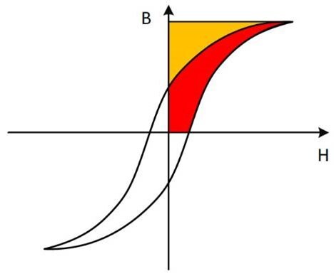
B is measured as H is increased. The response of B versus H is nonlinear and exhibits hysteresis, hence the name hysteresis loop. Hysteresis is one of the core-material characteristics that will cause power losses in the inductor core. A typical B-H curve is shown in figure 1 when a sinusoidal excitation is applied to the core.
Energy loss due to the changing magnetic energy in the core during a switching cycle equals the difference between magnetic energy put into the core during the on time, and the magnetic energy extracted from the core during the off time.
By using Ampere’s & Faraday’s Law, the Energy in the core can be expressed as:
Energy lost in the core is the area traced out by the B-H loop multiplied by the core’s volume. The power loss is this energy (E) multiplied by the switching frequency.
This expression applies on the conditions that the core is not driven into saturation, and the switching frequency lies in the intended (linear) operating range. The hysteresis loop area (red region in fig 1) represents energy loss. Power loss depends on how many times per second the hysteresis loop is traversed. Thus, hysteresis loss varies directly with frequency.
Fig 1: B-H Curve
The second type of core loss is due to eddy currents, which are induced in the core material by a time-varying flux ( ∅/ ). According to Lenz’s Law, a changing flux induces a current that induces a flux in opposition to the initial flux. This eddy current flows in the conductive core material and produces losses of 2 .
4. Determination of Losses
Historically, core losses are estimated by using power equation (1), also called Steinmetz equation.
is the core loss (Hysteresis & Eddy current loss) for unit volume, is peak flux density of a sinusoidal excitation, , & are the constants, derived from core loss graph shown in Figure 2.
The data given in figure 2 for core losses usually includes the effects of both hysteresis and core eddy currents.
Core-loss measurements are difficult because they require complicated setups for measuring flux density and because they involve the estimation of hysteresis-loop areas. For plotting these curves, a sine wave is applied to a toroidal (ring) core with 1 or 2 coil winding with 1 turn and extracts various data to plot the core loss chart. Then the constants are calculated using the graph in figure 2.
The major drawback of the Steinmetz equation is that it is mostly valid for sinusoidal excitation. This is a huge drawback because in most power electronic applications, the Inductor is usually exposed to non-sinusoidal flux waveforms. Even though there are other models which separates hysteresis & eddy current loss to overcome the problem of non-sinusoidal waveforms, the empirical Steinmetz equation has proven to be the most useful tool for sinusoidal flux-waveforms, because it provides better accuracy and is quite simple to use. Hence there are extensions to this power equation to make it accurately effective for non-sinusoidal flux waveforms.
Figure 2: Core Loss graph plotted against peak flux density at different frequencies
In order to utilize the Steinmetz equation for non-sinusoidal waveforms to estimate core losses, a later extension, “the Modified Steinmetz Equation” (MSE) (2) has been utilized widely.
being the equivalent frequency with respect to change in the duty cycle (DC) of non-sinusoidal waveforms.
Due to some disadvantages posed by MSE, later brought forth the Generalized Steinmetz Equation (GSE) to be developed - as shown in the equation.
Hence, as the GSE & MSE core loss charts are also based on sinusoidal excitation, there exists some limitations which will be discussed later. There also exist some other models developed by core manufacturers which works best with the cores only manufactured by them.
The major disadvantages of the Steinmetz and its extended models are:
- Dependent on Core Manufacturer’s empirical data, (for core loss charts). One must depend on the core manufacturer’s data and the passive component manufacturer does not have any control over the test setup
- Low accuracy with pulsating and triangular waveforms. Because the core loss graphs are created using the data from sinusoidal excitation
- Due to errors occurred in parameter conversion, the extension of Steinmetz models works best only for 50% duty cycle and limited frequency range
- Only confine to components made with particular materials or by manufacturer
- Due to the complexity of estimating Magnetic path length, the estimation of core loss using existing models for Iron Powder materials & Metal Alloys is not only challenging, but the accuracy varies widely
- Due to change in flux density with respect to time, there also exist losses in the component winding due to skin effect, proximity effect etc. and the above methodologies fail to include AC losses of the winding
- Unable to estimate losses in the component which has more than one material
- Complexity of the set up to produce accurate empirical data
5. The Würth Elektronik AC Loss Model
Würth Elektronik eiSos has developed state of the art model, allowing customers to effectively select the inductor and optimize the system. The model is based on the empirical data, derived from real time application set up.
In the Würth Elektronik eiSos model the total loss of the Inductor is divided into two separate losses as AC loss and DC loss. The power dissipation occurs due to DC current in the inductor windings and will be listed as the DC loss. The additional power loss occurred due to AC flux swing in the coil and the core is termed as AC loss.
The DC-DC converter as shown in figure 3 is utilized to produce an empirical data. A pulsating voltage is applied over the Inductor and the power Input, are measured, then = − is estimated and then AC loss of the Inductor is separated. This process is repeated over wide range of parameters including variation of peak flux density swing, frequency, ripple current, etc., to produce the empirical data. This empirical data is then used to create an equation to calculate AC loss in the form of = (Δ , , , 1, 2).
Fig 3: Setup of DC-DC Converter for Loss Determination and resulting scope shots
The hysteresis loops shown in the typical core material data sheets represent the core overdriven by a sinusoidal waveform from + to - saturation and the hysteresis loop area represents energy loss shown in figure 4a. This is the same approach used to produce empirical data for the core loss charts as shown in figure 2.
But in an SMPS application, the core is usually driven by a much smaller rectangular waveform with peak flux density limited by core losses to a minor hysteresis loop as shown in figure 4b. Power loss depends on how many times per second the hysteresis loop is traversed. Thus, hysteresis loss varies directly with frequency. The hysteresis loop changes shape somewhat with wave shape, current or voltage drive, and temperature. This variability, makes it very hard to predict core loss accurately. The minor loop area depends on the voltage above the Inductor. This minor loop is followed by the point of operation approach of Würth Elektronik to produce empirical data for Würth Elektronik’s AC loss model. Hence, this approach has proven robust, accurate over wide range of parameters like frequency, ripple current and duty cycle.
Fig 4a & 4b: Typical modelling used for Steinmetz equation and it’s extensions on the left and Würth Elektronik’s point of operation approach on the right
Advantages of Würth Elektronik’s AC loss model:
- Hence the empirical data is purely based on real time parameters with accurate estimation of losses for any given Duty Cycle being achieved
- The model is also accurate over wide range of frequency (10 kHz to 10 MHz) as the constants of the power equation are derived over a wide range with respect to the flux swing
- Considers even small change in core material and winding structure
- Valid for the components, which have more than one material
- Accurately estimates losses of Iron powder and Metal alloy materials
- Valid for any core shape and winding structure
- Includes AC winding losses
6. Performance of the Würth Elektronik AC Loss Model
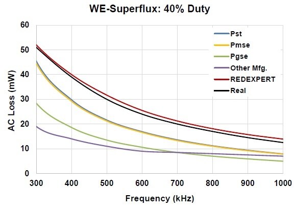
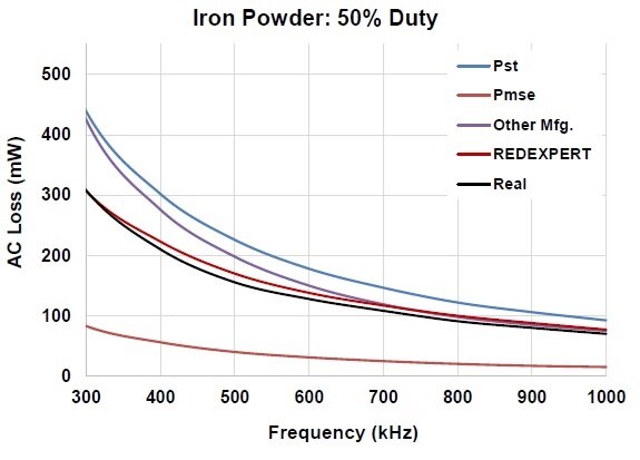
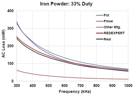
Würth Elektronik model has been validated extensively and compared with existing models and measured data. The AC loss for various materials like WE-Super flux , Iron powder, NiZn, MnZn, etc., are measured at a wide range of duty cycles, frequencies and other parameters compared with theoretical models as shown in figures 5 to 9. In below charts Pst, Pmse, Pgse are core losses determined using Steinmetz power equation, the Modified Steinmetz equation and the Generalized Steinmetz equation respectively. REDEXPERT is the AC loss calculated using Würth Elektronik AC loss model. Real is the measured AC loss.
Fig 5: Inductor made of WE Superflux at 40% DC Fig 6: Inductor made of MnZn material at 50% DC
Fig 7: Inductor made of MnZn Material at 33% DC Fig 8: Inductor made of Iron powder at 50% DC
Fig 9: Inductor made of Iron Powder Material at 33% DC
7. Determination of Power Inductor Losses with REDEXPERT
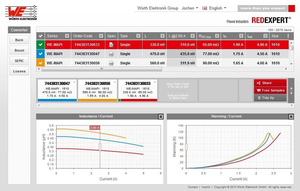
REDEXPERT is Würth Elektronik’s new online component selection and simulation tool which gives an option to the customer to select an appropriate power inductor based on the application. REDEXPERT is simple and effective tool, which allows an engineer to compare and select the inductors in no time. Once, the user enters their input and output parameters in the desired topology, the tool will calculate the inductance value and display the inductor choices. A screenshot of REDEXPERT web tool is shown in figure 10.
Fig 10: Screenshot of the REDEXPERT online tool
Since, Würth Elektronik eiSos has a wide range and variety of inductors, there is a good possibility that the user is filled with options. Then the user can chose the inductor according to the size & performance which suits the application. Calculating AC loss in a magnetic component is critical and complex, but not with REDEXPERT as the new Würth Elektronik AC model is implemented in this tool. With AC loss being calculated accurately, the estimation of temperature of a component is also apt with the application.
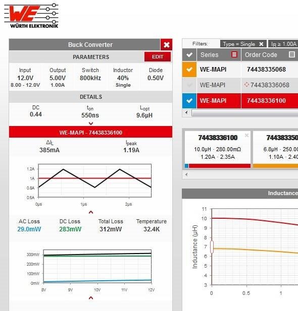
An example is shown in figure 11. A buck converter has been chosen. The operational parameters are 8 – 12 V is given as the input voltage, 5 V is given as output, switching frequency as 800 KHz, with inductor ripple as 40% and output current as 1 A. The REDEXPERT tool has estimated the optimal inductance (Lopt) as 9.6 μH, Ton as 550 ns and duty cycle as 0.44 and it has displayed more than 200 inductors to choose from. Let’s assume that the application requires miniature and low loss Inductor, the WE-MAPI series is the one we have chosen.
Currently REDEXPERT has three topologies Buck, Boost and SEPIC where the user can select the component for those applications. Furthermore, there is a Loss calculator for single inductor irrespective of the topology. REDEXPERT is a web based tool and the user does not have to bother about downloading and updates.
Fig 11: Buck-Converter Example
8. Summary
The Würth Elektronik’s AC loss model is accurate and practical model for determining AC losses. The model has been experimentally verified over wide range of frequency, ripple currents and duty cycles and proved to be robust. Due to the fact that this AC loss model is implemented in REDEXPERT, the user does not have to request core loss charts. Overall, REDEXPERT is power online calculation tool saves the engineer’s time in determining the losses and selecting the right component.
References
- Magnetics Design for Switching Power Supplies by Lloyd H. Dixon
- On the law of hysteresis by C.P. Steinmetz
- "Calculation of losses in ferro- and ferrimagnetic materials based on the modifiedSteinmetz equation" by Reinert, J.; Brockmeyer, A.; De Doncker, R.W.
- "Improved calculation of core loss with nonsinusoidal waveforms by Jieli Li; Abdallah, T.; Sullivan, C.R.
IMPORTANT NOTICE
The Application Note is based on our knowledge and experience of typical requirements concerning the areas, serves as general guidance and should not be construed as a commitment for the suitability for customer applications by Würth Elektronik eiSos GmbH & Co. KG. The information in the Application note is subject to change without notice. This document and parts thereof must not be reproduced or copied without written permission, and contents thereof must not be imparted to a third party nor be used for any unauthorized purpose.
Würth Elektronik eiSos GmbH & Co. KG and its subsidiaries and affiliates (WE) are not liable for application assistance of any kind. Customers may use WE’s assistance and product recommendations for their applications and design. The responsibility for the applicability and use of WE Products in a particular customer design is always solely within the authority of the customer. Due to this fact it is up to the customer to evaluate, where appropriate to investigate and decide whether the device with the specific product characteristics described in the product specification is valid and suitable for the respective customer application or not.
The technical specifications are stated in the current data sheet of the products. Therefore the customers shall use the data sheets and are cautioned to verify that data sheets are current. The current data sheets can be downloaded at www.we-online.com. Customers shall strictly observe any product-specific notes, cautions and warnings. WE reserve the right to make corrections, modifications, enhancements, improvements, and other changes to its products and services.
WE DOES NOT WARRANT OR REPRESENT THAT ANY LICENSE, EITHER EXPRESS OR IMPLIED, IS GRANTED UNDER ANY PATENT RIGHT, COPYRIGHT, MASK WORK RIGHT, OR OTHER INTELLECTUAL PROPERTY RIGHT RELATING TO ANY COMBINATION, MACHINE, OR PROCESS IN WHICH WE PRODUCTS OR SERVICES ARE USED. INFORMATION PUBLISHED BY WE REGARDING THIRD-PARTY PRODUCTS OR SERVICES DOES NOT CONSTITUTE A LICENSE FROM WE TO USE SUCH PRODUCTS OR SERVICES OR A WARRANTY OR ENDORSEMENT THEREOF.
WE products are not authorized for use in safety-critical applications, or where a failure of the product is reasonably expected to cause severe personal injury or death. Moreover WE products are neither designed nor intended for use in areas such as military, aerospace, aviation, nuclear control, submarine, transportation (automotive control, train control, ship control), transportation signal, disaster prevention, medical, public information network etc. Customers shall inform WE about the intent of such usage before design-in stage. In certain customer applications requiring a very high level of safety and in which the malfunction or failure of an electronic component could endanger human life or health customers must ensure that they have all necessary expertise in the safety and regulatory ramifications of their applications. Customers acknowledge and agree that they are solely responsible for all legal, regulatory and safety-related requirements concerning their products and any use of WE products in such safety-critical applications, notwithstanding any applications-related information or support that may be provided by WE. CUSTOMERS SHALL INDEMNIFY WE AGAINST ANY DAMAGES ARISING OUT OF THE USE OF WE PRODUCTS IN SUCH SAFETY-CRITICAL APPLICATIONS.
USEFUL LINKS
Application Notes: http://www.we-online.com/app-notes
Component Selector: http://www.we-online.com/component-selector
Toolbox: http://www.we-online.com/toolbox
Product Catalog: http://katalog.we-online.de/en/
DIRECT LINK
ANP029: Accurate Inductor Loss Determination using REDEXPERT
CONTACT INFORMATION
Würth Elektronik eiSos GmbH & Co. KG
Max-Eyth-Str. 1, 74638 Waldenburg, Germany
Tel.: +49 (0) 7942 / 945 – 0
Email: appnotes@we-online.de


