APPLICATION NOTE
Voids in Bottom Termination Components (BTC)
ANP036, BY DORIAN DEGEN AND MOHAMMED USAMA
1. Abstract
The market for Bottom Termination Components (BTCs) representative of QFN and DFN package is rapidly increasing in the electronic industry as the key drivers are - miniaturization and costs.
BTC's have brought new challenges in design and assembly processes, when these package types were introduced in the market. The large areas of the solder terminals bring many advantages with them, like dissipating heat of the component. However, if the assembly process is not properly adjusted than this can cause voids under the component.
The amount of voids can be influenced by different adjustments such as solder pastes with special solvents and grain sizes, thickness of solderpaste print on landpattern, the solder profile, the land pattern design, the solder stencil design and the surface of the PCB.
This application note was created with respect to work carried out to evaluate the challenges of voids on the WE-MAPI (DFN) products. Various techniques were implemented and tests were carried out, in order to resolve this issue such as - custom land pattern designs, optimization of reflow profile, custom stencils, push off tests etc. A brief description of the findings, techniques and tests implemented are discussed in this report.
2. A Brief Insight
Voids in solder joints are a consequence of outgassing from within the solder joint when the solder paste is in molten form, i.e. one can say that voiding is proportional to outgassing when the solder paste is in molten form which implies voiding is greatly dependent on flux chemistry. Voids are influenced greatly by wetting of the solder. I.e. better the wetting, lesser the flux entrapment in the solder joint in the molten state. In other words, if we can exclude the flux from within the solder joint, the outgassing of the flux will not contribute to the voiding of the BTC packages.
Overall, the wetting process is of more importance than outgassing. This can be taken care of, by using higher melting energy, which comprises of higher peak temperature and longer dwell time.
3. Work Flow
3.1. Custom Land Pattern
It is a known technique to implement a cross hatch pattern on the thermal pads of the large QFN–package ICs, such as processor ICs. Similarly, the idea of custom land patterns of different geometries and orientations was implemented and subjected to experimentation. The main aim was to see, if the wetting process of the solder paste was faster than the outgassing process, which would result in stronger joints and voids reduction. The land patterns were purposely made a little bigger than the foot print of the WE-MAPI in order to get a meniscus and to accommodate for the outgassing process.
Keeping in mind the points mentioned above, land patterns of various orientations and pitches were designed. Pre-tests were carried out, to check as to which land pattern would yield the best result. After the pretest the 180° rectangles and distributed squares showed to have best results as shown below:
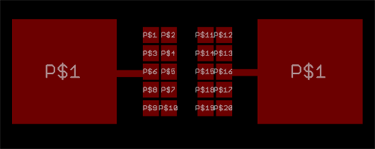 | 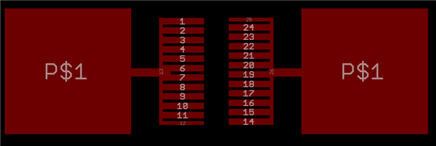 |
Figure 1: Distributed squares (for MAPI size 3mmx3mm) | Figure 2: 180° Rectangles (for MAPI size 3mmx3mm) |
3.2. Reflow Profile
We have used lead free solder paste (SAC alloys) for experimentation purposes. It is a common understanding that reducing the solder paste will help in minimizing voids. This is usually implemented by making a pattern on the stencil on a solid land pattern. At the same time one should also account for the lesser flux per unit area w.r.t the land pattern due to smaller, -solder paste printing. As a result of the reduced flux per unit area, the solder paste does not have enough flux to avoid the solder paste from drying out and oxidize during the reflow process.
Ramp to peak or Ramp to spike is the reflow profile that was developed considering the smaller solder paste print deposit sensitivity and higher temperatures. This profile is basically aimed at reducing thermal stress and total heat input but this profile is seen to strain the solder paste. Especially for smaller paste deposits and in order to avoid voiding to a certain extent a soak profile was implemented.
A reflow profile was designed with an extensive trial and error method to implement the following points:
- The implemented reflow profile was ramp –soak – spike (RSS).
- Linear ramp rate (approx. 1 °C/sec) – This minimizes the overall number of problems associated with the reflow process, for example: solder balling, solder beading and hot slump – leading to bridging effects etc.
- Soak zone – is important to minimize voiding. It assists in a faster wetting process than outgassing and in turn it helps in avoiding the tombstoning effects (keeping in mind the light weight of MAPI components).
- Peak and Time Above Liquidus (TAL) were in accordance with the recommendations of standards and datasheets. (Peak temperature of 265°C and little longer TAL of about 90 sec).
- Cooling stage -a drastic cool down is desired in order to obtain a fine grain structure. Slow cooling down will result in a large grain structure which typically exhibits poor fatigue resistance. A cool down ramp of almost 6°C/sec could be realized.
Note: The reflow profiling was in accordance with IPC/JEDEC J-STD-020D, refer to the same for further details.
3.3. Discussions and Results
Before going into the results of the conducted tests and experimentations, below shown are some results from the MAPI products with original land pattern:
 |  |
Figure 4: Lake Voids | Figure 5:Lake Voids |
One can see clearly the lake voids (figure 4 and 5). These voids result in weakening the joint and act as thermal insulators.
This results in faster increase of the inductor temperature, during inductor operation, as they obstruct the transfer of heat from the inductor to the PCB.
3.3.1. Pre– Tests Discussions and Results
Below shown are the CT scan results for the land patterns, which yielded the best results.
 |  |
Figure 6: Distributed Squares | Figure 7: 180° rectangles |
From the CT scans one can clearly see that the lake voids are completely eliminated but smaller voids still prevail the details of which will be discussed a little later.
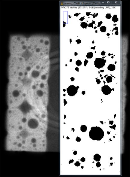
Note: Stencil thickness of 120 μm was used and the rhombus shaped patterns that are visible in Figure 6 are due to the shape of the land pattern and are not actual voids.
Stencil legend:
 |  |
| Non-Solid Stencil | Solid Stencil |
Shown below are the voids area calculation for Figure 6:
The area of voids was calculated to be 14.96%.
There exists no standard/norm which specifies the proportion of voids in a solder joint for BTC components. According to IPC610 30% of voids are allowed for BGAs and this was taken as reference for our analysis.
Figure 9: IPC610
Push of tests results:
Push of tests were the tests carried out, to check for the terminal break strength of the components. An illustrative figure is shown below for better understanding:
 Figure 10: push off test setup for terminal strength estimation reference standard: AEC-Q200-006
| WE-MAPI | ||
| Non solid stencil | Solid stencil | |
| 180° | 150.95 N | 157.95 N |
| Squares | 128 N | 127.25 N |
Table 1: Push off tests results
The push off force with the normal land pattern was just around 60 N.
After looking at the results from pre–tests as shown above, extensive testing with distributed square land pattern for further analysis was carried out.
3.3.2. Statistical Tests and Results
Furthermore, in order to validate our results the same testing and analysis pattern was applied to a large number of specimens. Here, the solder paste was changed from what was used in the pre –tests. The fine pitch capability of this solder paste used for statistical tests was 0.3mm. Two stencils of 100 μm and 120 μm thickness were used.
For statistical tests, different pitch sizes on the distributed square land pattern were implemented (0.1 mm and 0.2 mm), in order to compare and study the results.
Below shown are the CT results from statistical tests:
 |  |
| Figure 11: Sqaures, 0.1mm pitch land pattern | Figure 12: squares, 0.2mm pitch land pattern |
We can see from the scans that soldering finish on the land pattern with 0.2 mm pitch is much better than on the land pattern with 0.1 mm pitch. Where as in figure 6 the solder finish is much better on the same land pattern with a 0.1mm pitch size. The reason is, the fine pitch capability of solder paste which was 0.2 mm in pre-tests and 0.3 mm in statistical tests. Henceforth the solder finish in figure 12 is much better than that in figure 11.
Note: the pitch of the stencil and the land pattern are always the same. Below shown are the voids area calculations for fig 10:
Figure 13: Void area calculation for figure 10 (left pad)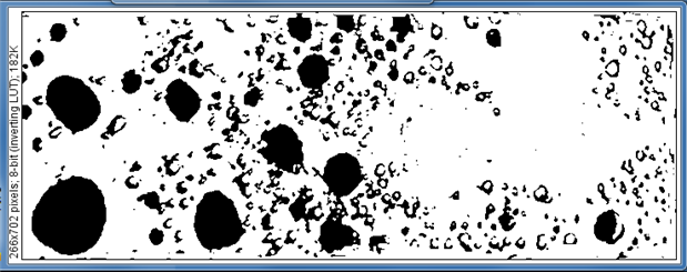
Area of voids was calculated to be 21.10%
Note: The red circled area in figure 11 is not accounted for voids calculation. It is not actually a void rather a place devoid of solder paste itself. It is due to the land pattern design and bad solder finish because of the higher fine pitch capability of the solder paste than the pitch size of land pattern itself.
Figure 14: Void area calculation figure 11 (left pad)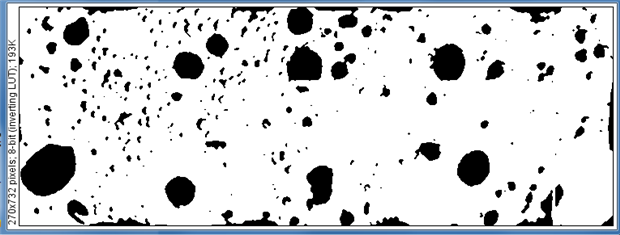
Area of voids was calculated to be 14.2%
Below shown are the results from the push off tests:
| 0.3 mm Fine Pitch capability solder paste | ||
0.1 mm pitch land pattern | 0.2 mm pitch land pattern | |
| Squares | 123.7 N | 110.98 N |
Table 2: Push off tests results
The solder joint strength was also tested with a 0.2 mm fine pitch capability solder paste, the results are shown below:
| 0.2 mm Fine Pitch capability solder paste | ||
| 0.1 mm pitch land pattern | ||
| Squares | 131.51 N | |
Table 3: Push off tests results
From the results above shown in table 2 and 3 the difference in the solder joint strength can be seen clearly.
Note: The push off test results shown here are the average values.
4. Summary
The main agenda of avoiding lake voids in our bottom termination components (BTC) with a dual flat package was successively achieved. There was no decrease in the solder joint strength, rather a dramatic increase in the same (from 60 N to 120 N approx.). Using a vacuum reflow oven or any other non-oxygen medium reflow, will help in voids reduction to a large extent.
All in all, voids are a boon as much as they are bane (like friction for instance). One should fathom the fact, that voids are an unavoidable phenomena when it comes to the bonding of two different metals in a molten state, in a non-vacuum environment. They basically act as stress absorbers or relievers and avoid the propagation of cracks within the solder joints. Complete absence of voids will actually result in higher tension in the joints eventually leading to developments of cracks in the joints. What can only be of concern are the lake voids. These trap air and act as thermal insulators. This in turn leads to a faster increase of the effective temperature rise of the component and a decrease in the overall solder joint strength. These lake voids were effectively eliminated without influencing any electrical parameters such as DCR, rated current, saturation current etc., by the techniques discussed in this application note.
IMPORTANT NOTICE
The Application Note is based on our knowledge and experience of typical requirements concerning these areas. It serves as general guidance and should not be construed as a commitment for the suitability for customer applications by Würth Elektronik eiSos GmbH & Co. KG. The information in the Application Note is subject to change without notice. This document and parts thereof must not be reproduced or copied without written permission, and contents thereof must not be imparted to a third party nor be used for any unauthorized purpose.
Würth Elektronik eiSos GmbH & Co. KG and its subsidiaries and affiliates (WE) are not liable for application assistance of any kind. Customers may use WE’s assistance and product recommendations for their applications and design. The responsibility for the applicability and use of WE Products in a particular customer design is always solely within the authority of the customer. Due to this fact it is up to the customer to evaluate and investigate, where appropriate, and decide whether the device with the specific product characteristics described in the product specification is valid and suitable for the respective customer application or not.
The technical specifications are stated in the current data sheet of the products. Therefore the customers shall use the data sheets and are cautioned to verify that data sheets are current. The current data sheets can be downloaded at www.we-online.com. Customers shall strictly observe any product-specific notes, cautions and warnings. WE reserves the right to make corrections, modifications, enhancements, improvements, and other changes to its products and services.
WE DOES NOT WARRANT OR REPRESENT THAT ANY LICENSE, EITHER EXPRESS OR IMPLIED, IS GRANTED UNDER ANY PATENT RIGHT, COPYRIGHT, MASK WORK RIGHT, OR OTHER INTELLECTUAL PROPERTY RIGHT RELATING TO ANY COMBINATION, MACHINE, OR PROCESS IN WHICH WE PRODUCTS OR SERVICES ARE USED. INFORMATION PUBLISHED BY WE REGARDING THIRD-PARTY PRODUCTS OR SERVICES DOES NOT CONSTITUTE A LICENSE FROM WE TO USE SUCH PRODUCTS OR SERVICES OR A WARRANTY OR ENDORSEMENT THEREOF.
WE products are not authorized for use in safety-critical applications, or where a failure of the product is reasonably expected to cause severe personal injury or death. Moreover, WE products are neither designed nor intended for use in areas such as military, aerospace, aviation, nuclear control, submarine, transportation (automotive control, train control, ship control), transportation signal, disaster prevention, medical, public information network etc. Customers shall inform WE about the intent of such usage before design-in stage. In certain customer applications requiring a very high level of safety and in which the malfunction or failure of an electronic component could endanger human life or health, customers must ensure that they have all necessary expertise in the safety and regulatory ramifications of their applications. Customers acknowledge and agree that they are solely responsible for all legal, regulatory and safety-related requirements concerning their products and any use of WE products in such safety-critical applications, notwithstanding any applications-related information or support that may be provided by WE. CUSTOMERS SHALL INDEMNIFY WE AGAINST ANY DAMAGES ARISING OUT OF THE USE OF WE PRODUCTS IN SUCH SAFETY-CRITICAL APPLICATIONS.
USEFUL LINKS
Application Notes: http://www.we-online.com/app-notes
REDEXPERT Design Tool: http://www.we-online.com/redexpert
Toolbox: http://www.we-online.com/toolbox
Product Catalog: http://katalog.we-online.de/en/
DIRECT LINK
ANP036: Voids in Bottom Termination Components (BTC)
CONTACT INFORMATION
Würth Elektronik eiSos GmbH & Co. KG
Max-Eyth-Str. 1, 74638 Waldenburg, Germany
Tel.: +49 (0) 7942 / 945 – 0
Email: appnotes@we-online.de


