APPLICATION NOTE
High Power Wireless Power Transfer
for the Industrial Environment
ANP032 BY ANDREAS NADLER AND CEM SOM
1. Introduction
As the presence of wireless power transfer technology increases in consumer electronics, the industrial and medical industries are shifting focus towards this technology and its inherent advantages. As communication interfaces are becoming increasingly wireless with technologies like WLAN and Bluetooth, wireless power transfer has become a relevant option. Completely new approaches can be taken that not only offer obvious technical advantages, but also open up possibilities for new industrial design. This technology offers new concepts - especially in industrial sectors struggling with tough environmental conditions, aggressive cleaning agents, heavy soiling and high mechanical stresses (e.g. ATEX, medicine, construction machines). For instance, expensive and susceptible slip rings or contacts can be substituted. Another field of application is with transformers, which have to satisfy special requirements, such as reinforced or doubled insulation.
The target of this Application Note is to demonstrate that easy-to-achieve solutions for wireless power transfer of one hundred Watts or more are reachable using circuit technology, without the need of software or controllers.
2. ZVS Oscillator (Differential Mode Resonant Converter)
A classical resonant converter is used as the clocking circuit in this Application Note.
This oscillator offers multiple benefits
- It oscillates independently and only requires a DC source
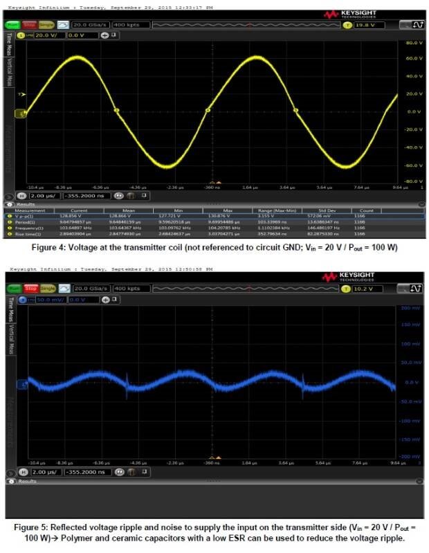
- The current and voltage profile is almost sinusoidal
- No active components and no software are needed
- It is scalable from 1 W – 200 W
- The MOSFETs switch close to the zero crossover point
- It is scalable for many different voltages/currents
2.1. Basic Circuit / Schematic:
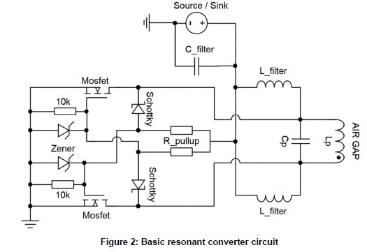
The basic circuit shown here is the transmitter side incl. transmitter coil LP. The receiver side can be constructed with the same Basic circuit (see chapter 3.1).
2.2. Functionality
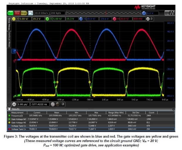
The resonant converter usually operates at a constant working frequency, which is determined by the resonant frequency of the LC parallel resonant circuit. As soon as a DC voltage is applied to the circuit, it starts to oscillate based on the MOSFETs component tolerances. Within a fraction of a second, one of the two MOSFETs is slightly more conductive than the other. The positive feedback of the two MOSFET gates and the opposite drain of the less conductive MOSFET gives rise to a 180° phase shift. The two MOSFETs are therefore always driven out of phase and can never conduct simultaneously. The MOSFETs alternately connect both ends of the parallel resonant circuit to ground allowing the resonant circuit to be periodically recharged with energy.
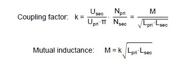
Another feature of this circuit topology is that the voltage always switches close to the zero crossover point, meaning the switching losses in the MOSFETs are very low. The disadvantage of this switching topology is that the power consumption in the idle state is relatively high due to the reactive currents circulating in the resonant circuit. For this reason, the resonant converter should ideally only be operated with a load. It should be considered that the frequency of the resonant circuit changes with the coupling factor of the receiver side. This arises due to the reflected impedance from the receiver side, which influences the magnetizing inductance of the transmitter side, as both sides are in parallel. A decreasing coupling factor causes the frequency to rise, as the magnetizing inductance of the transmitter side Drops.
The basic circuit from Figure 1 can run with voltages from 3.3 V up to and above 230 V, depending on the components used. Above input voltages of 20 V, attention must be paid to touch protection, as the voltage in the resonant circuitis already above the SELV (Safety Extra Low Voltage) threshold of 50 VAC / 120 VDC by a factor of π or more.
The efficiency of the entire wireless power transfer circuit may exceed 90% in practice. This is quite remarkable as the coupling losses via the air gap are already included and a steady DC voltage is available at the input. The efficiency remains stable within an air gap range of 4-10 mm. A large share of the energy in the magnetic field, which is not coupled to the receiver side, is returned to the “tank circuit”. A maximum distance of up to 18 mm is possible depending on the application however, concessions are made in terms of coupling factor and EMC.
The circuit on the transmitter side can be used identically for the receiver side. The resonant converter then works as a synchronous rectifier. Here it needs to be considered that the resonant frequency of the receiver side should be very closely matched to that of the transmitter side. This also generates a maximum “absorption circuit effect”. The parallel connection of C and L means that the secondary side behaves like a constant current source for the load. This allows the overall efficiency of the circuit to be raised significantly. In addition, the capacitor compensates the stray inductance of the wireless powercoil. If the circuit is prepared properly (i.e. …..) then the receiver can feed energy back to the transmitter (i.e. “Ideal” diode from Linear Technology at the load).
The efficiency can be raised by using smaller MOSFETs rather than Schottky diodes for driving the gate or by using a bipolar push-pull stage (see application examples). For supply voltages over 20 V, a capacitive voltage divider can be used to drive the MOSFET gates or a DC/DC converter (like the highly efficient and compact Würth Elektronik MagI³C Power Module) as an auxiliary voltage
as an auxiliary voltage source (see application examples in section 3).
Likewise, on the receiver side, instead of a resonant converter, a classical bridge rectifier can also be used. The advantage is a higher output voltage, lower costs and space savings at the cost of efficiency, due to diode losses. The frequency under load should generally not exceed 150 kHz, otherwise the losses in the Parallel capacitors, transmitter and receivers coils become too high. Additionally, the EMC limit values are higher beneath150 kHz (e.g. CISPR15 EN55015 9 kHz - 30 MHz). The frequency range 105 – 140 kHz emerged as the best compromise in tests carried out so far. This range also ensures that you remain in a safe range according to the currently approved frequency band for inductive power transfer (100 – 205 kHz).
If the end product will be launched in several countries, the regulations and permissible frequency bands should be ascertained for each country beforehand to speed up the development phase.
2.2.1. EMC Properties of Wireless Power Transformers
As power is transferred with all wireless power applications, compliance with the EMC limits are non-trivial. The challenge is that the transmitter and receiver coils behave like a transformer with a poor coupling factor and very large air gap. This leads to a very high stray electromagnetic field in the vicinity of the coils. EMC measurements have shown that broadband interference can occur in the spectrum of the fundamental wave through to the frequency range of 80 MHz. If the level of interference measured is kept below the limit with a reserve, it may be assumed that the limits of the interference field strength are also maintained. Generally speaking, the limit from, e.g. EN55022 Class B, may represent a development challenge which is not to be underestimated.
As the E field (stray field) is the main cause of EMC problems in WPT applications, the appropriate measures
have to be adopted:
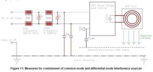
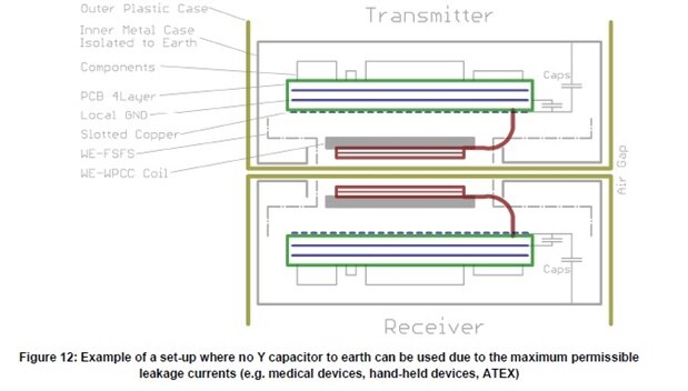
A. In order to reduce eddy currents, there should be slotted metal plane (e.g. PCB with copper) under the WPT coil (especially transmitter) and oriented towards the circuit. The circuit has to be connected via a capacitor (e.g. 1-100 nF / 2000 V WE-CSMH) to the circuit ground or case. This short-circuits a large proportion of the E field to the source and it no longer propagates via earth.
B. Shield the transmitter and receiver coils and their drives with sufficient metal shielding and/or absorber material (WE-FAS/WE-FSFS).
C. If the leakage currents allow, Y capacitors (2x4.7 nF max.) can reduce the interference levels over a broad spectrum (WE-CSSA).
D. In order to filter common mode interference sources in the low frequency range (50 kHz – 5 MHz), depending on the operating voltage and current, the current-compensated (common mode) chokes from the following series can be used: WE-CMB / WE-CMBNC / WE-UCF / WE-SL / WE-FC
E. In order to filter common mode interference sources in the higher frequency range (5 MHz – 100 MHz), depending on the operating voltage and current, the current-compensated chokes from the following series can be used: WE-CMB NiZn / WE-CMBNC / WE-SL5HC / WE-SCC
F. Suppressing differential mode interference and depending on the operating voltage, capacitors from the following series can also be connected between +/- L/N: WE-FTXX / WE-CSGP
G. As very high AC currents flow in the entire circuit, depending on the application, a compact and low inductance PCB layout is essential for success in EMC. The components of the power stage and the resonant circuit should be placed very close to each other and connected with low inductance using large copper areas (polygons).
Generally it is recommended to work with a competent EMC lab during development to measure Performance throughout the design process. Changes in mass production are always associated with higher expenses and additional workload (limits for electromagnetic field strength).
2.2.2. Transmitter and Reciever Coils
In order to find the suitable wireless power transfer coil, some aspects should be considered first:
- How high is the maximum current anticipated (reactive and rated current) in the coil?
- What is the maximum permissible package size (L/W/H)?
In order to avoid unwanted saturation or over-temperature of the coils, a safety buffer of 30% should always be planned for. If several coils can be incorporated, those with the highest inductance should be used, as the resonant circuit capacitor can then be smaller. Additionally, this measure reduces the reactive currents occurring in the “tank”. Smaller currents in the resonant circuit lead to lower self-heating and to better EMC properties.
The best coupling is achieved when the transmitter and receiver coils have the same package size hence, a size ratio of 1:1 is recommended. The components from the WE-WPCC Family (e.g. 760308102142 (53mmx53mm), 760308100143 (ø 50mm), 760 308 100 110 (ø 50mm)) were specially developed for high power. These coils can be used as transmitters and receivers. They are characterized by very low Rdc values very high Q values and very high Saturation currents IR.
2.2.3. Parallel Capacitor
Because high currents circulate in the parallel resonant circuit, not every capacitor technology is suitable for this task. Depending on the application, only three different types are available for selection: MKP (e.g. WE-FTXX) (WE-FTBP), NP0 (e.g. WE-CSGP) or FKP. On account of their low loss factor, these capacitor types are capable of sustaining high AC currents without overheating. However, depending on the power of the resonant converter, it is not uncommon to switch several capacitors in parallel to divide the currents and the self-heating. Care should be taken that none of the capacitors become warmer than 85°C. As a result of their higher loss factors (especially dielectric losses), X7R, X5R, MKS etc. are not suitable for resonant converters. In consideration of the package size, costs and the lowest possible reactive current in the resonant circuit, the capacitance should be chosen to be as low as possible. Here the limiting factors are the converter’s
maximum working frequency, as well as the level of transmitter and receiver coil inductance. The voltage stability should be at least π · Vin, plus an additional 20% safety reserve. It also has to be considered that the maximum permissible VACrms voltage for MKP capacitors drops markedly at frequencies below 5 kHz.
2.2.4. Filter Inductors
The two filter inductors moderately decouple the “AC” resonant circuit from the supply. At the same time, they also serve as a constant current source and filter element. The current carrying capacity has to be adapted to the maximum rated current of the circuit. A classical power inductor (e.g. WE-HCI; WE-PD; WE-LHMI) with air gap and high Q factor always has to be used. Its rated inductance should be at least 5 times higher than the inductance of the WPT coil in order to be in a position to reload sufficient energy into the resonant circuit. If the input/output ripple is still too high, the values of the filter inductor or capacitor can be increased. Alternatively, the filter components’ ESR can be reduced for the same effect on the ripple. Flat wire power inductors (WE-HCF/WE-HCI) are advantageous in keeping AC and DC losses as low as possible at high currents. Since these inductors have to constantly reload a high AC current to the resonant circuit, considerable self-warming occurs due to the hysteresis and eddy current losses in the core material. The level of inductance required is directly related to the capacitance of the filter capacitor. Further information is in section 2.2.7.
2.2.5. MOSFETs
Suitable selection of the N-MOSFETs primarily depends on the level of the supply voltage. If this is just 5 V, for example, a logic level type has to be used for driving the gates reliably. As most power MOSFETs have a maximum gate voltage of +/- 20 V, measures have to be taken to protect the gates in case of a supply voltage above 20 VDC. This may be a Zener diode to ground or a capacitive voltage divider, which keeps the gate voltage in the optimal range. Care must also be taken that the voltage at the gate is not too low, otherwise a MOSFET in the resonant converter will get stuck in linear amplifier operation mode, causing the circuit to enter a latch-up state. This usually leads to overheating of one of the two MOSFETs. Furthermore, care must be taken to prevent voltage overshoots of a factor of pi greater than the supply voltage. For example, at 20 Vcc, the MOSFETs have to withstand a drain-source voltage of at least 63 V. In this case 100 V_DS types should be used. The efficiency of the circuit depends significantly on how high the “On” resistance (Rdson) and gate charge (total gate charge) of the MOSFETs are. A compromise has to be found here, as MOSFETs with low Rdson usually have a higher total gate charge.
2.2.6. Diodes and Pull-ups
As the MOSFETs have to be recharged relatively quickly, fast currents in the high Ampere range arise with the charge and discharge of the gate. These charging/discharging currents have to be routed via the pull-up resistors and the diodes. The losses arising are not negligible. For this reason, the maximum allowed power loss (Pv) and the current carrying capacity of these components have to be chosen appropriately. Likewise, the diodes must have the same voltage stability as the MOSFETs. As an alternative to classical diodes or Schottkys, the body diodes of MOSFETs can also be used. Depending on the type, they can display beneficial properties at a high temperature, which are usually stated in the datasheet. The reverse recovery losses should also not be underestimated and have to be considered.
2.2.7. Input and Output Capacitor
These capacitors, in combination with the power inductors, serve mainly as filters. As the resonant frequencies are below 200 kHz, the capacitors have to be correspondingly higher. Tests have shown that values between 10 and 1000 μF are to be anticipated, depending on the application and power inductors used. The -6 dB cutoff frequency resulting from the LC filter should be around 1/10 of the resonant circuit frequency. In theory, attenuation of 40 dB / dec is expected. Taking parasitic component effects into consideration, 30 dB / dec should be expected in practice. Depending on the filter coil used, a significantly high AC current component can be superimposed on the DC current. If this current is too high, an aluminum polymer capacitor can be used in place of an aluminum electrolytic capacitor to withstand large AC currents. Polymer and ceramic capacitors, with their low ESR, also offer the possibility of significantly reducing the amplitude of the reflected voltage ripple. A smaller voltage ripple means that there is a lower interference level in the EMC interference measurement. The best result is obtained by using a parallel connection of aluminum electrolyte capacitors and polymer or ceramic capacitors (e.g WCAP-PTHR/WCAP-PSLC).
2.3. Pitfalls with the Resonant Converter
Two things in particular have to be considered in practice with this circuit topology to prevent latch-up of the MOSFETs.
1. The power supply of the transmitter at the moment of switching
If the power supply is not in a position to deliver sufficient current during transient oscillation of the circuit, it may occur that one of the two MOSFETs gets stuck in linear amplification mode and the input voltage permanently shorted to ground. This would cause the MOSFET to overheat and suffer permanent damage. Attention should also be paid that the input filter capacitor is not over-dimensioned, which could possibly further exacerbate this “latch up” effect, as the power supply has more capacitance to charge. This effect can be avoided in practice by connecting the capacitors and the resonant circuit to the operating voltage before the rest of the circuit. The gates of the MOSFETs can then be switched via optocouplers or transistors. The gates can also be driven via a separate voltage source (e.g. Würth Elektronik MagI³C Power Module) whose switchin is delayed from the supply.
2. The impedance reflected from the receiver side to the transmitter side
Given large load jumps on the receiver side or sudden changes in the coupling factors of the two coils, it may
occur that the reflected impedance partially short-circuits the magnetizing inductance of the transmitter side.
This, in turn, can lead to the oscillation breaking down and the circuit going into a “latch-up” state.
To counteract this, it is helpful to slightly detune the frequency of the receiver resonant circuit with the aid of another parallel capacitor (10 - 20% higher frequency than the transmitter). Alternatively, an additional inductance (power inductor) can be connected in parallel to the transmitter coil, which has no magnetic coupling with the transmission path. This parallel inductance has to be equal to or less than the magnetization inductance of the transmitter coil. This parallel inductance stores energy during the ZVS process and helps to maintain the oscillation in the event of unfavorable load transients.
In the first prototype phase it is important to test out all conceivable load situations, as far as this is possible, to ensure a robust design with proper functionality.
2.4. Optimization of the WPT Coil Environment
If the WPT coils are secured on metal, there may be inductive losses due to induced eddy currents caused by the magnetic stray field. In addition, the metal close by (e.g. copper on PCBs) may heat up inadvertently. Electronic circuits can also be inadvertently influenced by the strong magnetic stray fields. This effect will be higher with increased separation of the WPT coils.
Suitable measures include increasing the separation of the coils to the PCB/metal, as well as the use of highly permeable ferrite foil, such as WE-FSFS. Thus, the magnetic flux is specifically directed and is not converted into heat. This also allows the coupling factor, and therefore the efficiency, to be raised. These self-adhesive and flexible ferrite foils are available in several sizes and thicknesses.
3. Application Examples
3.1. Simple Receiver Circuit
TVS Power Diode to protect against transient over-voltages (bidirectional; max. operating voltage 60 V).
Please Note: Observe precautionary measures and touch protection with voltages above 50 VAC / 120 VDC!
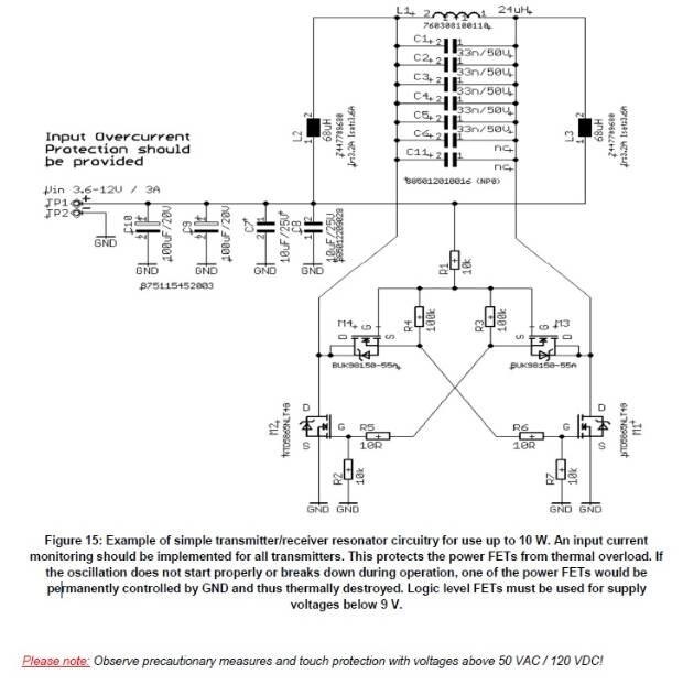
3.2. Standard Resonant Converter (Transmitter and Receiver up to approx. 10 W)
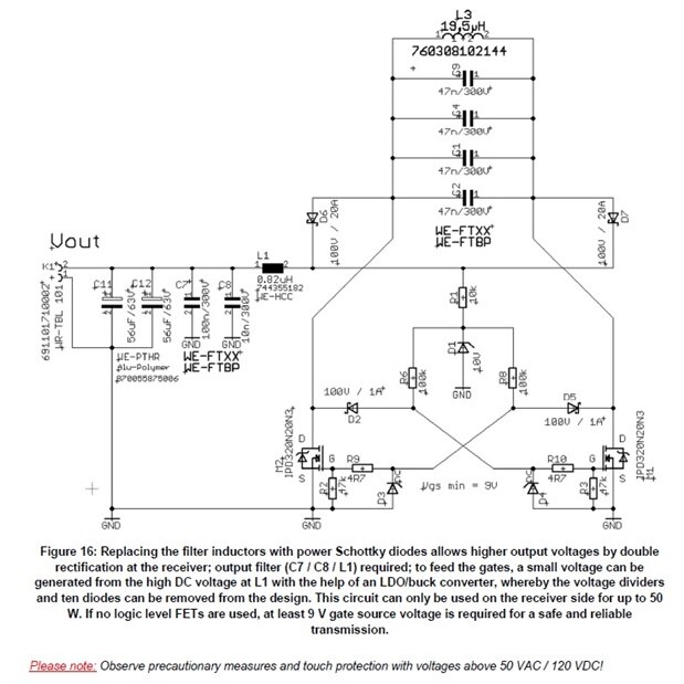
3.3. Example of a Modified Receiver Circuit (up to approx. 50 W)
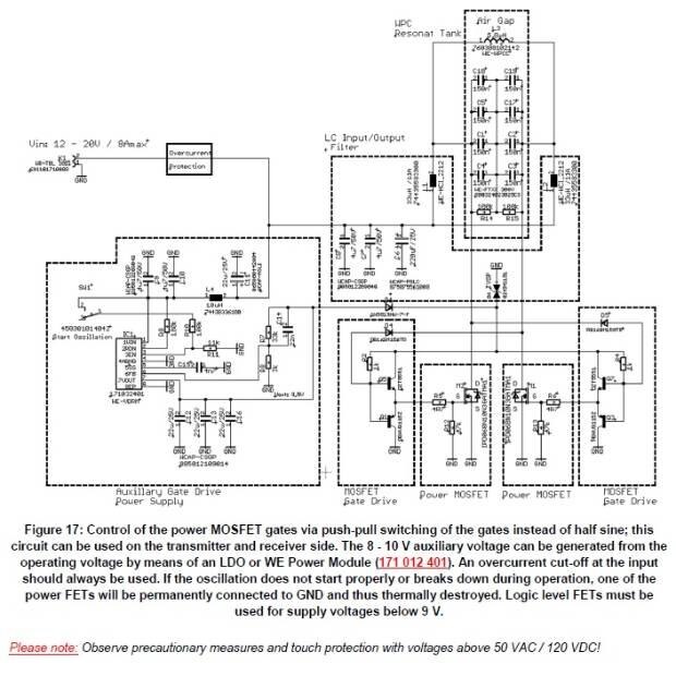
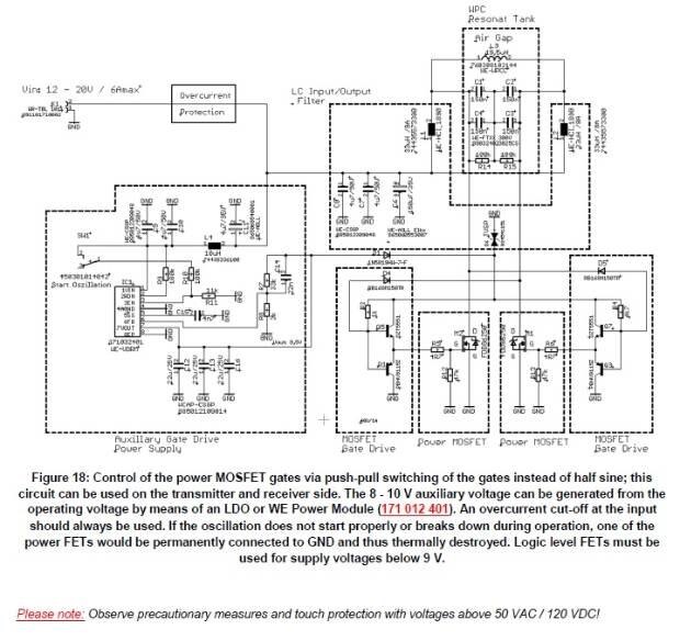
3.4. Example of Push-Pull Gate Control (Transmitter and Receiver up to approx. 100 W)
3.5. Example of Push-Pull Gate Control (Transmitter and Receiver up to approx. 60 W)
3.6. Example of Push-Pull Gate Control (Transmitter and Receiver up to approx. 30 W)
3.7. Application of a Double Resonant Converter (up to 20 V / 8 A max.)
3.8. Application of a Resonant Converter with Center Tap (up to 30W)
Figure 22: Construction for application example transmitter/receiver 3.9 for coil array (760308104119).
4. Summary
This resonant converter is very flexible and can be adapted to the requirements of many different applications this circuit currently represents the most effective wireless transfer of energy of up to several hundred Watts. If the demands of the application grows in terms of safety, On/Off, charging state detection etc., this circuit can serve as the basis and be extended by the hardware developer. A classical H bridge circuit with active regulation can also be taken as the basis rather than the resonant converter topology. In any case, EMC measurements should be performed on the first prototypes at an early stage during development. High efficiency, the most compact package and good EMC properties essentially depend on the clocking circuit, as well as the transmitter and receiver coils. Besides the widest product range, Würth Elektronik also offers coils with the highest Q factors in their respective packages. This allows higher inductance values to be attained and results in smaller packages for the capacitors.
In addition, HF litz (stranded) wire is used exclusively for high power (lower AC losses) with high quality ferrite material (high permeability). This means the maximum efficiency and best possible EMC performance for the end product.
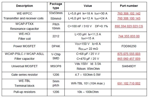
5. BOM for application example of Digikey
IMPORTANT INFORMATION
The application information based on our current state of knowledge and experience serves as general information and is not assurance from Würth Elektronik eiSos GmbH & Co. KG as to the suitability of the product for customer applications. The application information may be changed without prior notice. This document and parts thereof may not be reproduced or copied without written consent. Würth Elektronik eiSos GmbH & Co. KG and its partners and subsidiaries (together hereinafter referred to as "WE") are not liable for any kind of application-related support. Customers are entitled to use
WE's support and product recommendations for their own applications and designs. The responsibility for applicability and use of WE products in a particular design is borne exclusively by the customer in every case. Based on this fact, it is the customer's responsibility to initiate any investigations necessary and to decide whether or not the device with the specific product features described in the product specification is approved and suitable for the respective customer application.
The technical data are specified in the current data sheet for the product. For this reason, the customer has to use the data sheets and attention is expressly drawn to the fact that they have to ensure the data sheets are up to date. The current data sheets can be downloaded from www.we-online.com. The customer must strictly observe product-specific remarks and warnings. WE reserves the right to undertake corrections, modifications, additions, improvements and other amendments to its products.
Licenses and other rights of any kind, especially to patents, utility models, marks, copyrights or other commercial protection rights are hereby neither granted nor shall any duty be implied to grant such rights. By publishing information on third-party products or services, WE neither grants a license to use such products or services nor offers a guarantee or endorsement for them.
The use of WE products in safety-critical applications or those in which severe personal injury or death can arise due to product failure is not permissible. Furthermore, WE products are neither designed for nor intended for use in fields such as military technology, aerospace, nuclear control, navy, transportation (control of motor vehicles, trains or ships), traffic control installations, civil protection, medical technology, public information networks etc. The customer must inform Würth Elektronik of the intention of such use before the start of the planning phase (design-in phase). For customer applications with stringent safety requirements in which the malfunction or failure of an electronic component could endanger life and limb, customers must ensure that they have the required expert knowledge of the safety and legal implications of their applications. Customer acknowledge and agrees that, notwithstanding all application-related information and support provided byWE, they bear full responsibility for all legal, statutory and safety related requirements in conjunction with their products and the use of WE products in such safety-critical applications. The customer shall indemnify and hold Würth Elektronik harmless with respect to all claims arising from such safety-critical customer applications.
USEFUL LINKS
Application Notes: http://www.we-online.de/appnotes
REDEXPERT Design Tool: http://www.we-online.de/redexpert
Toolbox: http://www.we-online.de/toolbox
Product catalog: http://katalog.we-online.de/
CONTACT INFORMATION
Würth Elektronik eiSos GmbH & Co. KG
Max-Eyth-Str. 1, 74638 Waldenburg, GERMANY
Phone: +49 7942 945 - 0
Email : appnotes@we-online.de

