

RANGE ESTIMATOR APPLICATION NOTE
VERSION 1.0
DECEMBER 2, 2019
1 Introduction
When a radio connection is planned the given circumstances define largely the requirements for radio range, operating temperature and available space. To ease the challenge of choosing a suitable RF-module regarding the radio range Würth Elektronik eiSos makes freely available the Range Estimator to find on the website http://www.we-online.com/redexpert . With this tool the modules can be sorted and selected by their attributes. After selecting a module and maybe changing the radio profile and antenna height it shows the calculated range for the Friis model and for the two ray ground reflection model. This application note explains the theory behind the two models, the requirements, differences and the reasonable use.

Figure 1: RedExpert

Figure 2: Range Estimator Overview
2 Graphical User Interface
In order to use the Range Estimator properly, a basic understanding of the selectable attributes is required. The first step is to select a module which is suitable for the application. This will preconfigure the input boxes to a default set of values for the Range Estimator Tool corresponding to the specific data sheet These presets are typical conditions, and may need to be adjusted by the user.
For example, the antenna height has to be adjusted to the utilized height, as this impacts the two ray radio range. Equally the use of an other radio profile with for example a higher data rate would degrade the receiver sensitivity and consequently the radio range.

Figure 3: Range Estimator GUI
3 Fresnel zone

Figure 4: Fresnel zone ideal simplified
| Character | Description | Unit |
| c0 | speed of light in vacuum | [m/s] |
| dtotal | distance from transmitter to receiver | [m] |
| f | the frequency of the transmitted signal | [Hz] |
| Fn | radius of the n-th Fresnel zone | [m] |
|
Fnmax | maximum radius of the n-th Fresnel zone between transmitter and receiver |
[m] |
| λ | wavelength of the transmitted signal | [m] |
| n | number of the Fresnel zone | |
| x | point on the line of sight between transmitter and receiver | [m] |
The Fresnel zones are ellipsoids around the line of sight between the transmitter Tx and the receiver Rx with the antennas in its focal point. There are multiple Fresnel zones around the line of sight. If an object is within the Fresnel zone in a matter, that a 2-segment path from Tx to Rx deflects off a point within that border. This corresponds to a time-of-arrival difference between the line of sight and the reflected signal from objects, for the primary Fresnel zone of between 0°and 90°, for the second between 90°and 270°, for the third between 270°and 450°and so on. The primary Fresnel zone is the most important to keep free, because most of the signal power will be transmitted in this area.
The radius of the any Fresnel zone at any chosen point on the line of sight x is calculated by the equation
(1)
so the equation for the radius on any chosen point on the line of sight is
(2)
this formula makes the assumption, that x and dtotal x both are much longer than n λ, for the first Fresnel zone this means that x and dtotal x have to be much longer than the wavelength of the signal.
Due to this restriction the radius will not be accurate for distances close to the Tx- or Rx- antenna.

Figure 5: The changing radius of the Fresnel zone for different frequencies with a dtotal of 1000 meters
The Fresnel zone shows the largest diameter for x = dtotal x - x = dtotal x /2 , which is actually right in the middle between Transmitter and Receiver.
To get an impression on which objects may cause power loss of the signal, it is often useful to know at least the maximum diameter of the first Fresnel zone. Which according to (1) is.
 (3)
(3)
The dependency of the maximum radius from the frequency and the transmission distance is shown in this graph.
Obviously the radius of the Fresnel zone will increase for longer distances between Transmitter and Receiver. But also the frequency of the transmitted signals has a major influence to the radius of the Fresnel zone.
A 2.44 GHz Signal will have an 8.5 meters maximum radius for a line of sight distance of 2350 meters. Will the signal be transmitted with a frequency of 868 MHz a maximum radius of 8.5 meters will only allow a line of sight distance below 850 meters. As a short reminder, any object within the first Fresnel zone will damp the transmitted signal and reduce the range of the transmission.

Figure 6: Radius of the Fresnel zone
4 Calculation models
Depending on the application it is often not possible to keep the Fresnel zone free of objects. So it is essential to understand, that this has high influence on damping of the transmission and therefore maintaining the range of a RF-module. But to estimate its range, a look on the specific datasheet is mandatory. There are several methods to calculate the range of a RF- transmission, but these equations are often very complex and unhandy for practical usage, so simplification is needed. The results of the simplified equations are only approximations, but experience shows that the discussed equations are able to deliver reliable estimations for the transmission range, when applied correctly. As a convention all symbols are in metric units, if not otherwise declared. To improve understanding of basic equations metric units are mandatory, but because logarithmic values are commonly used in radio communication, it is purposeful to also use the logarithmic units for the range calculation.
| Character | Description | Unit |
| λ | wavelength of the signal | [m] |
| 2RPL | path losses of the 2-ray ground reflection model | [dB] |
| c | speed of light in vacuum (299 792 458) | [m/s] |
| d | distance from transmitter to receiver | [m] |
| f | frequency of the signal | [m] |
| hT x | height of the transmitter antenna over ground | [m] |
| hRx | height of the receiver antenna over ground | [m] |
| FSPL | path losses of the free space model | [dB] |
| LM | link margin (safety to ensure a received signal) | [dB] |
| PT x | total power emitted by the transmitting antenna | [W] or [dBm] |
| PRx | total power received by the receiving antenna | [W] or [dBm] |
| Rxsens | sensitivity of the receiving RF module | [dB] |
4.1 Friis transmission for free space

Figure 7: Free space model
Friis transmission for Free Space is a model to calculate the path loss, to estimate the range of a radio link in a free space environment.
This model makes the assumption, that the emitted power is radiated equally in every direction (isotropic) and calculates the power loss only taking into account the decreasing power density of the wavefront with increasing distance to the origin, without any reflection, absorption or attenuation.
 (4)
(4)
this leads to the free space path loss
 (5)
(5)
expressed in decibel this means,

To determine the maximum range of a Wurth Elektronik eiSos RF-module, the path losses

Figure 8: Wave amplitude depending on the distance to the Tx antenna
of the transmission are equaled to the ratio of the received power to the emitted power:


Figure 9: Path losses for different frequencies
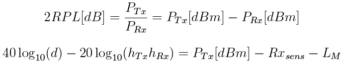
4.2 Two-ray ground reflection
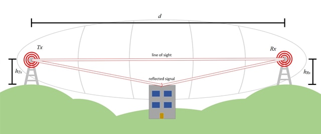
Figure 10: Two ray ground model
The two-ray ground reflection model is applied, when transmitter and receiver are in line of sight but the first Fresnel zone is not free ob objects. So the calculation consideres the received power of the direct line of sight path and in addition the power of the reflection path with slight phase difference. In the following a simplified formula is shown, giving suitable results for the precondition of long distance between receiver and transmitter compared to their antenna heights, d » ht + hr.:
 (8)
(8)
Which translates to
 (9)
(9)
and in decibel

A very interesting aspect now is, that the formula depends on the heights of both antennas but not on the frequency.
To determine the maximum range of a module, the path losses of the transmission are equaled to the ratio of the received power to the emitted power:
(10)
(11)

Figure 11: Path losses for different antenna heights
5 Conclusion
In a lot of cases there is the need of long distances with regard to the antenna height, so usually the two ray ground model is a good fitting estimation. Only for some special cases with the free space condition fulfilled the Friis model is useful.
Having a closer look to the models there are several interesting points to mention.
• One point is the dependency of the frequency. Often it is mentioned in general, that the lower the frequency is, the higher the range is. We have learned, that this is only the case when free field conditions are met. But there other effects of the frequency, as the fact, that for higher frequencies smaller objects will cause reflections, or that for low frequencies it might be hard to find an antenna with acceptable size and efficiency.
• An other important point is the influence of the antenna height on the range. The higher the antennas can be placed, the longer is the range that can be reached. Placing an antenna directly above ground reduces the range so radical, a layman could hardly imagine.
Often there is stated the free field range for radio modules. This might be useful to compare modules as the two ray ground model would differ depending on the chosen antenna height. But the risk is to underestimate the difference between this model and the practical reached range.
To illustrate, that the Friis model range can diverge extremely from the real accomplish able range, we compare the range estimations of the 2 models. Therefore we pick a module, from which we know, by empirical values and costumer feedback, that the 2-ray ground reflection model is very close to the real accomplished range. Our pick is the Thebe-II, a proprietary radio module at 869 MHz. We adjust the antenna heights to some realistic values, 6m for the transmitter and 6m for the receiver and use radio profile 3, which is one of the long range modes of Thebe-II. In the following screen shot ( 12) we can clearly see in this example, that the range estimation with the Friis model is almost up to twenty times higher, than the range that will be achieved in a real application.
Comparing the two models one point catching attention is the often large difference in the resulting range. This is easy explained by the formulas, as in the Friis model the distance is entered by the power of two, in the two ray model by the power of four.
By using the the Range Estimator on Redexpert tool range calculations can be cut, because the range estimation of the 2 ray ground model is pretty accurate.

Figure 12: Range estimations for Thebe-II
USEFUL LINKS:
Contact:
Würth Elektronik eiSos GmbH & Co. KG Division Wireless Connectivity & Sensors
Gottbillstr. 22
54294 Trier
Germany
Tel.: +49 651 99355-0
Fax.: +49 651 99355-69