


Disclaimer: In line with our RMA Terms & Conditions, the warranty on hardware devices shall be null and void if the product has been subject to improper installation. It is advised to carefully read the latest version of the HESAI PandarXT manual as well as the MTi product's Datasheet and Hardware Integration Manual (available here) before connecting your hardware.
Note: This tutorial will configure the MTi-G-710 and MTi-670 to output its data in response to their own GNSS 1 PPS signal. This means that the MTi will not provide any data as long as there is no valid GNSS time/position fix (except when using the CAN interface, refer to the end of this article for more details). Depending on the amount of satellites in view it can take several minutes until the 1 PPS signal is obtained by the GNSS receiver.
Introduction
This article describes how to interface your GNSS/INS device with a HESAI Lidar. HESAI Lidars accept a GPS input which allows their data to be correlated with position. For this purpose a GPS 1PPS signal and a 1 Hz RS232 $GPRMC or $GPGGA message are required. Both the MTi-G-710 and the MTi-670 support these outputs. HESAI however does have some communication and timing constraints for external GNSS/INS devices, which can be found in the HESAI PandarXT User Manual. Most importantly the MTi needs to be configured such that it transmits the RS232 message shortly after transmitting the 1 PPS signal. This article describes how to configure your MTi in order to meet these requirements.
The two setups presented in this article have been tested using a HESAI PandarXT32 Lidar.
The HESAI Lidar comes with an Connection Box that includes a terminals with connections for power, GPS communication and Ethernet. In this article the connections GROUND, +5V, PPS and GPS Receive are used.

Figure 1: HESAI Connection Box
Configuration
- Start by configuring your MTi-G-710 to output the correct NMEA string and time data. The easiest way to do this is by using our GUI, MT Manager, which is part of the MT Software Suite.
- In MT Manager, open the Device Settings window (
 ).
). - In the Output Configuration tab, select "String report mode" and choose "GPGGA" and/or "GPRMC". Choose "400 Hz" from the drop-down menu. Click Apply.
- In the Device Settings tab, set the COM port baud rate to 9600 bps. Click Apply.
- In the Synchronization Options tab, the "GNSS Clock In" feature should already be present in the list of configured settings.
- Click Add, and select the 1PPS Time-pulse function. Leave the other fields as is. This will create a 1 PPS signal on the SyncOut line of the MTi.
- Click Add, and select the Send Latest (In) function. Leave the other fields as is. This will configure the MTi to transmit its most recent data sample when triggered on the SyncIn line. We will later connect the SyncIn and SyncOut.
- Click Apply.
The circuit diagram in Figure 2 shows how to connect your MTi-G-710 to the HESAI Connection Box.
Please note the following:
- For testing purposes it is possible to power the MTi-G-710 directly using the 5V supply available in the Connection Box. We do however recommend powering the MTi-G-710 separately while meeting the requirements mentioned in the MTi User Manual.
- This setup can be realized by using the CA-MP2-MTi cable. The wire map for this cable can be found in the MTi User Manual.
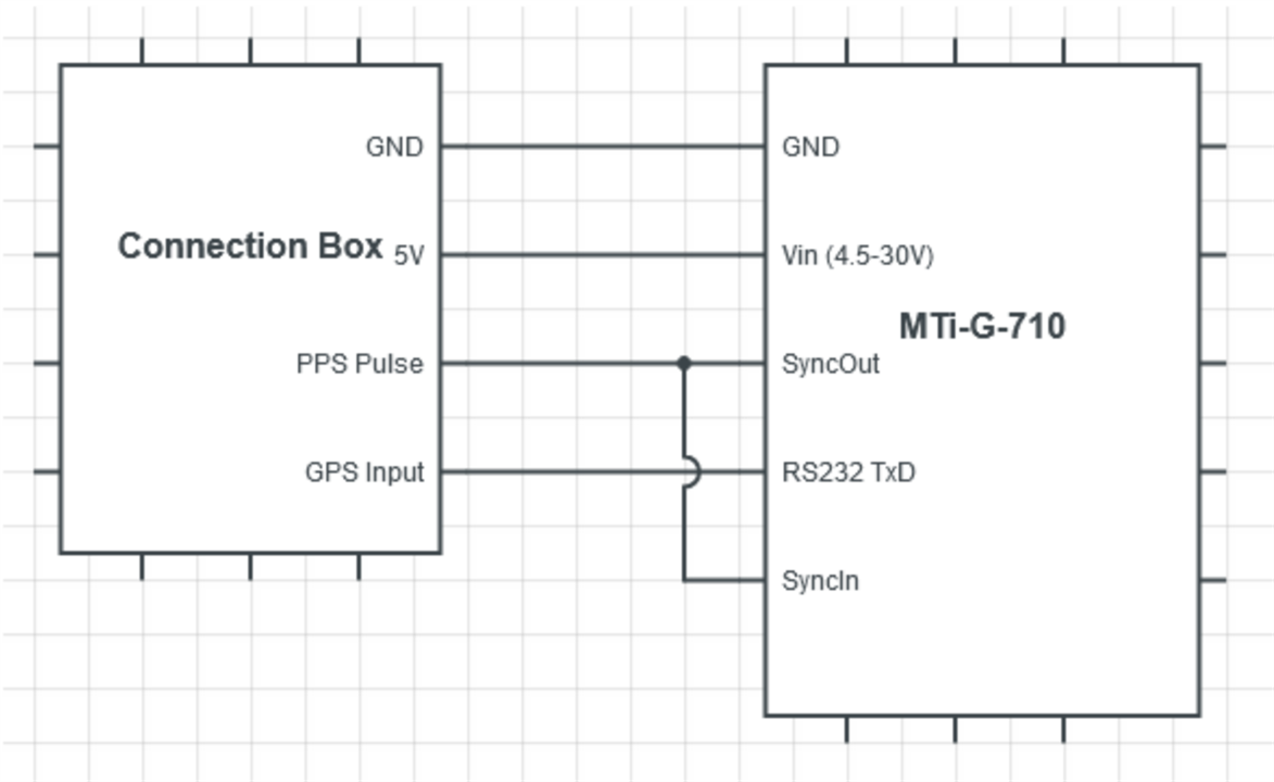
Figure 2: Interfacing the MTi-G-710 with the HESAI Connection Box.
Configuration
- Start by configuring your MTi-670 to output the correct NMEA string and time data. The easiest way to do this is by using our GUI, MT Manager, which is part of the MT Software Suite.
- In MT Manager, open the Device Settings window ().
- In the Output Configuration tab, select "String report mode" and choose "GPGGA" and/or "GPRMC". Choose "400 Hz" from the drop-down menu. Click Apply.
- In the Device Settings tab, set the RS232 Protocol to "String Output" and the RS232 baud rate to 9600 bps. Click Apply.
- In the Synchronization Options tab, the "Clock Bias Estimation (In)" and the "1PPS Time-pulse" features should already be present in the list of configured settings, both on line In 2.
- Click Add, and select the Send Latest (In) function. Choose Line "In 2". Leave the other fields as is. This will configure the MTi to transmit its most recent data sample when triggered by the 1PPS signal on the SyncIn2 line.
- Click Apply.
Interfacing
The circuit diagram in Figure 3 shows how to connect your MTi-670 to the HESAI Connection Box.
Please note the following:
- For testing purposes it is possible to power the MTi-670 directly using the 5V supply available in the Connection Box. We do however recommend powering the MTi-670 separately while meeting the requirements mentioned in the MTi 600-series Hardware Integration Manual.
- As mentioned in the MTi 600-series Hardware Integration Manual, the RS232 CTS line of the MTi-670 needs to be tied to a logical high (3-25V). Otherwise the MTi will not transmit data over the RS232 interface.
- This setup can be realized by using the MTi-670 Development Board. In that case the 1 PPS signal from the GNSS receiver daughter card is already connected to SyncIn2.
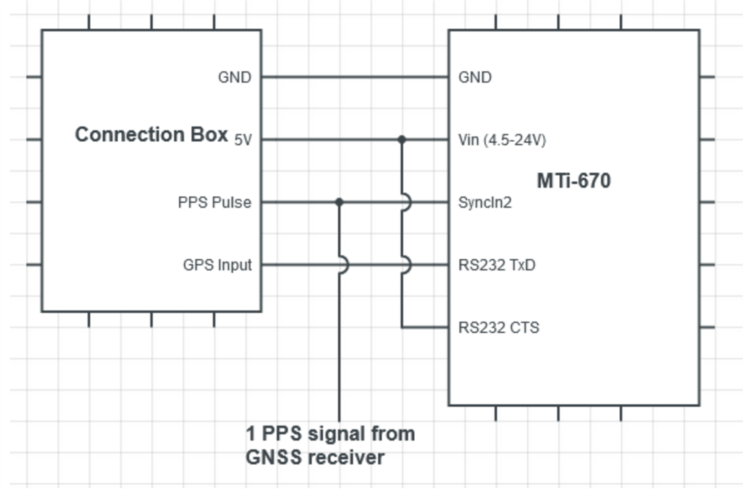
Figure 3: Interfacing the MTi-670 with the HESAI Connection Box.
Setup 3: MTi-670G/680G
In contrast to the MTi-G-710, the MTi-670G/680G does not yet offer a “true” 1 PPS output that comes straight from the internal GNSS receiver. Instead, by using the Interval Transition Measurement synchronization feature, the MTi-670G/680G can be configured to generate its own 1 PPS signal that is synchronized with the 1 PPS signal of the internal receiver. This pulse will be synchronized with the internal GNSS 1 PPS pulse in terms of frequency, but not in terms of phase. This means that the 1 PPS output of the MTi-670G/680G does not appear at the exact start of each UTC second. The timing of the pulse depends on the moment you power up the MTi.
The MTi-670G/680G does provide sub-second data in its NMEA messages, however some lidar brands do not copy the full UTC time information from the $GPGGA or $GPRMC packets: They often assume that the 1 PPS signal and its corresponding data packet coincide with the start of a UTC second, and therefore the sub-seconds field is assumed to be zero. This can cause a data timing error of up to 1 second.
Configuration
- Start by configuring your MTi-680G to output the correct NMEA string and time data. The easiest way to do this is by using our GUI, MT Manager, which is part of the MT Software Suite.
- In MT Manager, open the Device Settings window ().
- In the Output Configuration tab, select "String report mode" and choose "GPGGA" and/or "GPRMC". Choose "400 Hz" from the drop-down menu. Click Apply.
- In the Device Settings tab, set the RS232 port baud rate to 9600 bps and the Protocol to String Output. Click Apply.
- In the Synchronization Options tab, the "Clock Bias Estimation" and “1PPS Time-pulse” features should already be present in the list of configured settings.
- Click Add, and select the Interval Transition Measurement function. Set Skip Factor to 399. Leave the other fields as is. This will create a 1 PPS signal on the SyncOut line of the MTi.
- Click Add, and select the Send Latest (In) function. Leave the other fields as is. This will configure the MTi to transmit its most recent data sample when triggered on the SyncIn line. We will later connect the SyncIn and SyncOut lines.
- Click Apply.
Interfacing
The circuit diagram in Figure 4 shows how to connect your MTi-680G to the HESAI Connection Box.Please note the following:
- For testing purposes it is possible to power the MTi-680G directly using the 5V supply available in the Connection Box. We do however recommend powering the MTi-680G separately while meeting the requirements mentioned in the MTi 600-series Hardware Integration Manual.
- This setup can be realized by using the CA-MP-MTI-12 cable. The wire map for this cable can be found in the MTi 600-series Development Kit User Manual.

Figure 4: Interfacing the MTi-680G with the HESAI Connection Box.
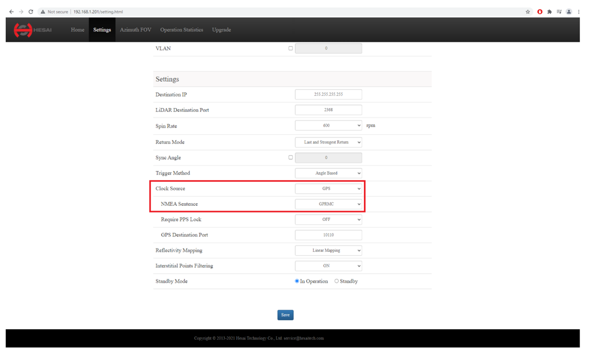
- Start by configuring your HESAI Lidar to recieve the MTi's sync signal and NMEA Data.
- For this example the Web Control Page (Pandar Console) was used. Configure the highlighted portions of HESAI Lidar's Settings as Shown below and click Save
- NMEA Sentence: GPRMC or GPGGA
- How can I check whether the 1 PPS signal and NMEA string messages are received properly?
You can use the Ethernet connection to open the HESAI User Interface (see below screenshot). The User Interface will show a real-time display of the GPS UTC Time and PPS status.
- Why does my MTi-G-710 not output $GPRMC data?
The $GPRMC message is only supported by firmware versions 1.10.0 and up. Check the firmware version of your device using MT Manager and if necessary, update to the latest firmware by using our Firmware Updater. The MTi-670 firmware has always supported the $GPRMC message.
- Can I configure the MTi to output other data next to the $GPRMC and/or $GPGGA strings?
The MTi can be configured to also output other (NMEA) string outputs when triggered by the 1 PPS signal, as long as the 9600 bps baud rate allows for it. Additionally, the MTi 600-series allows for outputting data over the UART (IP51 modules only) and CAN interfaces as well, in parallel with the RS232 interface. Both the UART and RS232 interface will then only report data when triggered by the 1 PPS pulse. The CAN interface does not support the SendLatest functionality and therefore it will simply transmit its data at the configured data rate.