
Welcome to the Xsens page on element14. Here you can find things such as our latest news, training videos, and product details. Additionally, you can engage with us in our forums.

If you think about automation in warehouses, what comes to mind? Maybe you think about Forklifts, Stackers, or Pallet Jacks? Well, we think about Mobile Warehouse Robots.
Mobile Warehouse Robots are (semi-) autonomous wheeled ground vehicles that transport materials or do some other logistic tasks. Traditionally they are called 'Automated Guided Vehicle' (AGV), but the 'Autonomous Mobile Robot' (AMR) will enter the stage as the latest advanced generation — with more intelligent and flexible navigation, having many sensors inside, e.g., Simultaneous Localization And Mapping ("SLAM"). This technology is similar to how the human brain works, combining memorized pictures of a situation with what eyes see.
Why Mobile Warehouse Robots will be crucial to a warehouse: Improve accuracy in material handling (picking, towing, conveying, moving)Reduce physical and mental strain on human workersAutomate tedious tasks
With the rapid change of technology, warehouse robots are changing every day. Are you wondering about the future of Mobile Warehouse Robots? Register for our online conference, and learn more about it. ️Conference detail:
 The Future of Mobile Warehouse Robots
 January 25th
 10:00 AM CET
 Online
 Join our conference for free via: https://bit.ly/TheFutureofMobileWarehouseRobots

Suppose you have ever been staying in a room on the upper floor of a hotel and felt like indulging in a late-night snack or drink, but resisted the urge because you could not face trailing all the way down to the vending machine in the lobby. In that case, you will appreciate the new JEEVES® room service robot from Germany-based Robotise.

The fully autonomous service robot, called JEEVES, is the world’s first to comply with the European Union’s safety regulations governing the operation of robots in public spaces. And to navigate its way around complex, crowded multi-storey buildings such as hotels and hospitals, it needs highly accurate, reliable 3D motion tracking data – a requirement met by the compact MTi-610 sensor from Movella.
Totally automated room service
The JEEVES service robot can move on-demand to any location in a building accessible by elevator. Its modular design is based on an efficient motor base, on which a custom combination of materials-handling containers is mounted. In a hotel scenario, the JEEVES platform can be stocked at its loading station with snacks, sweets, and drinks. In a hospital, it might carry medical consumables such as bandages, disinfectant wipes, and sterile gloves. In an office, the JEEVES robot can be loaded with items such as printer paper, pens, staples, and so on.

The JEEVES robot platform can be adapted for use in many different types of public spaces
Robotise’s smart and innovative technology enables fully autonomous delivery of service orders –JEEVES navigates from the loading station to any programmed location on any floor. Its capabilities include summoning an elevator via the Robotise Operations Center (ROC), a cloud service that gives users the 24/7 remote monitoring capability of a fleet of JEEVES robots.

Fully automated room service, courtesy of the JEEVES robot
In the hospitality sector, automation with the JEEVES robot enables a hotel to provide 24/7 room service, even though night when a single member of staff might run the front desk. In a hospital, the JEEVES robot frees valuable medical staff from the time-consuming task of answering service, rather than medical, calls from the wards, allowing them to focus their time on direct patient care.
All of this is possible because of Robotise innovations which ensure that the JEEVES robot can navigate through complex, unstructured environments and detect obstacles and avoid collisions with people in its immediate environment.
Reliable navigation in 3D space
The key to the reliability of the JEEVES robot’s fully autonomous navigation is a multi-mode sensor system, in which errors in one mode can be detected and corrected by another.
The primary method of navigation is a 3D ‘depth map’ derived from detailed LiDAR (infrared laser) scans of the entire building. These scans are tagged with essential location data such as room numbers and elevator doors.
The robot’s LiDAR sensors scan the environment as it moves around, matching the scene to the reference database of depth maps to establish the location and to plot a route to the destination. The LiDAR sensors also detect objects such as people so that they can be safely avoided. In a multi-storey building, the ROC system connects to the elevator control software, telling the robot which floor it is on.
These systems, however, can on occasion provide faulty or no information – for instance, inside an elevator the robot might lose its Wi-Fi® connection to the ROC cloud, and so miss the elevator’s signal telling it which floor it is on. In addition, some locations appear very similar – long, uniform hotel corridors are an example – which means the robot could potentially match its sensor data to the wrong map location on rare occasions. In crowded areas such as a hotel lobby, the LiDAR sensors’ view of the area can be so obstructed that the robot cannot match any known location on equally rare occasions.
This is where the alternative navigation mode kicks in, using precise motion data from a Movella MTi-610 series inertial measurement unit (IMU). The IMU produces an accurate stream of acceleration and rate-of-turn data in real-time. Through a process of dead reckoning, the robot uses the MTi-610 sensor’s outputs to calculate its movement in three dimensions from a known starting point.
By measuring vertical motion in this way, the JEEVES robot can accurately determine which floor it is on, even without a connection to the ROC cloud. And by measuring motion in the horizontal plane, the robot can track its approximate location continuously. This enables the robot to override an apparent LiDAR map match that is not consistent with the MTi-610 sensor’s data and move temporarily by dead reckoning until it can match to the LiDAR depth map with a high degree of confidence.
A compact, low-power IMU
Robotise selected the Movella MTi-610 series because its features are particularly well suited to fully autonomous operation on battery power. Compact – the unit has a footprint of just 28mm x 31.5mm and weighs less than 10g – the MTi-610 enables accurate dead reckoning calculations thanks to its low noise density and low drift. Typical power consumption of less than 500mW also helps the JEEVES robot to maintain day-long operation on battery power.
Tobias Riphaus, the Robotic Engineer at Robotise, says that the MTi-610 is a fail-safe back-up to the sophisticated LiDAR system of indoor navigation. ‘I have total confidence that the location information derived from the MTi-610 IMU is always going to be available to the JEEVES robot, and is going to be accurate enough to perform error correction on the LiDAR sensor. Robotise has tested the JEEVES platform exhaustively, in many different types of environments, and the MTi-610 sensor has never once let us down.’
The NVIDIA Jetson edge AI platform is widely used for the development of autonomous machines and robotics. In this article we will explain how to connect your Xsens MTi device to the NVIDIA Jetson hardware, and how to easily communicate with it by using our MT Software Development Kit (MT SDK).
NVIDIA Jetson Developer Kits run on ARM Cortex CPUs, which means that they are not compatible with the regular Xsens Device API. Fortunately, Xsens has made a large part of the API open source, allowing users to develop applications for ARM-based platforms as well. Xsens provides C++ example codes as well as a ROS driver that make use of this open source API.
We have used the Jetson Nano Developer Kit for this article, but the guidelines can also be used for other Jetson hardware. Xsens has tested the following motion trackers with the Jetson Nano:
Start by downloading the latest MT Software Suite for Linux from our website and unpack the .tar.gz package at your desired location. Then, install the MT SDK:
sudo ./mtsdk_linux-xxx_xxxx.x.x.sh
This article will cover two hardware interfaces of the Jetson Developer Kit: USB and TTL UART. If possible, we recommend using USB as a starting point, to verify that your hardware and software can detect and communicate with external sensors. Simply connect your MTi to one of the USB ports of the Jetson Developer Kit using the USB cable included in your Development Kit.
Inside the MT SDK you will find an examples folder. Open it and navigate to the xda_public_cpp folder. You will find two example codes:
In this folder, open a terminal and build the example codes:
sudo make
sudo make HAVE_LIBUSB=1
Inside the MT SDK you will find the xsens_ros_mti_driver. Simply follow the README.txt file inside this folder or our guidelines at http://wiki.ros.org/xsens_mti_driver to install and launch the ROS driver. Your MTi should be detected automatically, and a variety of data topics are available to subscribe to. We refer to the Troubleshooting section at the end of this article if the MTi is not detected.
Note: the ROS driver publishes data, but unlike the C++ example code, it does not actually configure the outputs of the MTi. Use the C++ example code or a PC with our GUI MT Manager to configure the MTi such that it outputs the data that are required for your application.
Next to the plug-and-play USB interface, Jetson Developer Kit offer various other interfaces that allow you to communicate with MTi devices. In the case of the Jetson Nano, we used a UART interface that is accessible via the J41 header, pins 8 (TxD) and 10 (RxD). We also used the 3V3/5V and GND pins on that same header to power the MTi.
Note: The UART interface of an MTi 1-series Development Board will be disabled when the board is powered at 5V. Use the 3.3V output of the Jetson Developer Kit instead.

In Ubuntu, this UART port will show up as /dev/ttyTHS1. By default, the ROS driver and C++ example code do not scan this location. Fortunately, it is easy to modify the source code such that it scans for your specific location:
Open example_mti_receive_data.cpp (in case of the C++ example code) or xsens_ros_mti_driver/src/xdainterface.cpp (in case of the ROS driver) and replace the following lines:
XsPortInfoArray portInfoArray = XsScanner::scanPorts();
XsPortInfo mtPort;
for (auto const &portInfo : portInfoArray)
{
    if (portInfo.deviceId().isMti() || portInfo.deviceId().isMtig())
    {
        mtPort = portInfo;
        break;
    }
}
with
XsPortInfo mtPort = XsScanner::scanPort("/dev/ttyTHS1",XBR_230k4);
Alternatively, the ROS driver also allows you to configure the desired port and baud rate manually without modifying the source code. To do so, uncomment and modify the following lines in the file xsens_mti_node.yaml, located at xsens_ros_mti_driver/param:
# port: '/dev/ttyUSB0'
# baudrate: 921600
You should now be able to detect and access the MTi via the UART interface.
sudo make HAVE_LIBUSB=1
sudo make HAVE_LIBUSB=1The MTi should now be recognized whenever you launch the ROS driver or C++ example code.
setserial [/path/to/xsens/port] low_latency
rostopic hz imu/data
add_custom_COMMAND(TARGET xsens_mti_node
PRE_BUILD COMMAND $(MAKE) --always-make -j 1 -C
${CMAKE_CURRENT_SOURCE_DIR}/lib/xspublic
)
Still facing challenges? Don’t hesitate to contact our Product Specialists for further support.
This article describes how to interface the MTi-680(G) with the Racelogic VBOX NTRIP modem in order to receive the RTK corrections from an NTRIP client.
NTRIP (Networked Transport of RTCM via Internet Protocol) is a protocol that enables streaming of RTK correction data via the internet over common TCP/IP methods. These NTRIP services can be accessed via paid subscription or free-to-use broadcasters. Here you can find a list of NTRIP casters and providers in different parts of the word: https://ntrip-list.com/
The Racelogic VBOX NTRIP is part of the Racelogic VBOX Systems which are used by vehicle and tyre manufacturers for testing and validating a vehicle’s performance, handling and safety systems. This NTRIP modem is used to receive positional correction data via an internet connection. The NTRIP configuration is made via a Wi-Fi access point and the front screen will display status and connection information.

Figure 1: Racelogic VBOX NTRIP modem
The circuit diagram in Figure 2 shows how to connect the RTCM connector of the MTi-680G to the Racelogic NTRIP modem.
This setup can be realized by using the CA-MP4-MTi cable. The wire map for this cable can be found in the MTi-600-Series Development Kit User Manual.
The pin description of the Racelogic NTRIP modem connector can be found in the Racelogic VBOX NTRIP modem User Guide.
The Racelogic NTRIP modem is using the main connector to output the RTCM messages. This connector must be connected to the RTCM correction port of the MTi-680G.

Figure 2: MTi-680G and Racelogic NTRIP modem connection
Please note the following power supply remark for the Racelogic NTRIP modem:
There are two ways for the Racelogic NTRIP modem to connect to an NTRIP server, namely via:
Start by configuring the MTi-680(G) RTCM port baud-rate settings and output configuration.


Once the MTi-680(G) is configured follow the instructions in the Racelogic NTRIP Modem Quick Guide to connect to an NTRIP client and start outputting RTK corrections.
Once the configuration is complete, the Racelogic NTRIP modem should be connected to an NTRIP client and receive-output RTK corrections:

Figure 3: RTK fix indication of Racelogic NTRIP modem
Once that is implemented, the received RTCM messages are forwarded to MTi-680(G).
After launching MT Manager, you should be able to confirm an RTK Float/Fix using the StatusWord message or the RTK Status flag:
The 5th bit from the left indicates RTK Float, the 4th and 5th bit from the left together indicate an RTK fix. More information regarding the contents of Status Word message can be found in the Low Level Communication Protocol Documentation.

Figure 4: StatusWord message in the Device Data View
 ra
ra
Figure 5: RTK high(fix) in Status Data window
The MTi-680-DK comes with an external RTK GNSS daughter card. In this case you can feed the Racelogic NTRIP modem RTCM corrections directly to the RTK GNSS daughter card.
The Racelogic NTRIP modem RTCM outputs must be connected to the XBee socket of the external MTi-680 DK RTK GNSS daughter card. The XBee socket pinning can be found in the MTi-600-Series Development Kit User Manual.
If you are powering the NTRIP modem via USB make sure you are using a high quality USB cable
If the problem persists power the NTRIP modem via an external power supply
Make sure you have an active internet connection (via Wi-Fi or GSM)
Make sure the antenna of the NTRIP modem has a clear view of the sky
Ensure that the NTRIP server you are connected to is not using base stations which are far away (>25 km) from your location, try another mount point or another NTRIP server
Check the baudrate RTCM port settings of MTi-680(G); the baudrate should be set to 115200
The GNSS antenna of the MTi-680(G) should have a clear view of the sky and the MTi-680(G) should report a GNSS Fix (GNSS flag high)
When testing or evaluating the MTi 1-series we highly recommend purchasing a Development Kit, such as the MTi-3 Development Kit or the MTi-7 Development Kit. The Development Board included in this Kit features many different options to communicate with your MTi 1-series device, such as a micro-USB interface and Arduino-compatible headers for UART, SPI and I²C communication.
In addition to this, the Development Board features two mikroBUS extension sockets, one for connecting an external GNSS receiver (MTi-7-DK only) and one for regular communication purposes. This latter communication port can be found on headers P202 and P203 as indicated in the figure below. For the exact pin descriptions, refer to the MTi 1-series DK User Manual.

The mikroBUS communication extension socket allows users to further extend the communication capabilities of the MTi 1-series Development Board. Because of the mikroBUS standard there are various off-the-shelf "click boards" available that can be mounted here, including boards for serial and wireless communication. Refer to Mikro Elektronika's webshop for a large range of available click boards.
The table below shows a list of transceiver click boards that have been tested with the MTi 1-series Development Board. For some click boards, additional configuration is necessary; see the configuration column.
| Board | Vendor link | Compatibility | Configuration |
| RS232 Click | Verified compatibility | Full-duplex: Set PSEL0/PSEL1 to 0/0. | |
| RS232 2 Click | - | Hardware flow control not supported; RTS/CTS pins reversed. | |
| RS485 Click 3.3V* | Verified compatibility | Half-duplex: Set PSEL0/PSEL1 to 1/0. | |
| Bluetooth Click | Verified compatibility | RST functionality needs to be disabled**. Can be configured to act as a serial bridge in Windows ("Standard Serial over Bluetooth Link (COM)"), making it fully compatible with the MT Software Suite. |
Notes:
If you have any questions regarding this list, please do not hesitate to contact our product specialists.
Some of Xsens' GNSS/INS devices, such as the MTi-7, MTi-670 and MTi-680, support the use of an external GNSS receiver. When testing or evaluating these products we highly recommend purchasing a Development Kit. The MTi-7-DK and MTi-670/680-DK include a Development Board, GNSS daughter card and GNSS antenna, which means that all required hardware is available to get started right away.
For the MTi-7-DK and MTi-670-DK, the included GNSS daughter card features the u-blox MAX-M8Q GNSS receiver, which is a commonly used, standard precision GNSS receiver. The MTi-680-DK comes with a GNSS daughter card that features the u-blox ZED-F9P. However, it is easy to connect any other desired type or brand of GNSS receiver. The GNSS extension socket on the Development Boards follows Mikro Elektronika's mikroBUS standard. This means that a wide variety of GNSS daughter cards (click boards) is available that can be directly mounted onto the Development Board's GNSS extension socket.

The table below shows a list of GNSS click boards that have been tested with the MTi-7-DK, MTi-670-DK and MTi-680-DK. For some click boards, additional configuration is necessary; see the configuration column.
| Board | Vendor link | Farnell link | Compatibility | Configuration |
| u-blox MAX-M8Q | Included with MTi-7-DK and MTi-670-DK | Verified compatibility and performance | - | |
| u-blox ZED-F9P | Included with MTi-680-DK | Verified compatibility and performance | - | |
| u-blox NEO-M8N | Mikro Elektronika | Farnell | Verified compatibility | - |
| u-blox NEO-M9N | Mikro Elektronika | Verified compatibility | Need to manually enable port UART1 at 115200 bps using u-center (UBX-CFG-PRT message). | |
| u-blox ZOE-M8Q | Mikro Elektronika | Farnell | Verified compatibility | - |
| u-blox SAM-M8Q | Mikro Elektronika | Farnell | Verified compatibility | Compatible with MTi-670-DK revision 1.7 (introduced Nov 2021) and higher. Compatible with MTi-7/680-DK (all versions). |
If you have any questions regarding this list, please do not hesitate to contact our product specialists.
It is also possible to connect GNSS receivers to the GNSS extension socket without following the mikroBUS standard. In that case it is recommended to connect the RX, TX, GND and PPS pins. TX (of the MTi) is only required when communicating with u-blox GNSS receives as the MTi will send out UBX configuration messages at power-up. The PPS signal is not required but recommended for proper time/clock synchronization. The GNSS extension socket also features a 3.3V pin that can supply power to the GNSS receiver (and its antenna), but depending on the type of GNSS receiver the provided current might not be sufficient.
The GNSS extension socket of the MTi 1-series Development Board only supports communication at UART TTL levels. The MTi 600-series Development Board also uses UART TTL communication by default, but a jumper can be placed at GNSS_DIS in order to enable RS232 communication.
Disclaimer: In line with our RMA Terms & Conditions, the warranty on hardware devices shall be null and void if the product has been subject to improper installation. It is advised to carefully read the latest version of the HESAI PandarXT manual as well as the MTi product's Datasheet and Hardware Integration Manual (available here) before connecting your hardware.
Note: This tutorial will configure the MTi-G-710 and MTi-670 to output its data in response to their own GNSS 1 PPS signal. This means that the MTi will not provide any data as long as there is no valid GNSS time/position fix (except when using the CAN interface, refer to the end of this article for more details). Depending on the amount of satellites in view it can take several minutes until the 1 PPS signal is obtained by the GNSS receiver.
Introduction
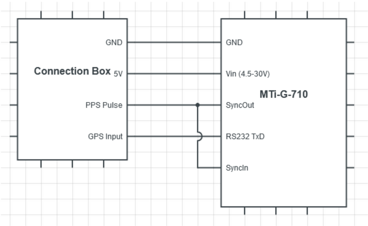
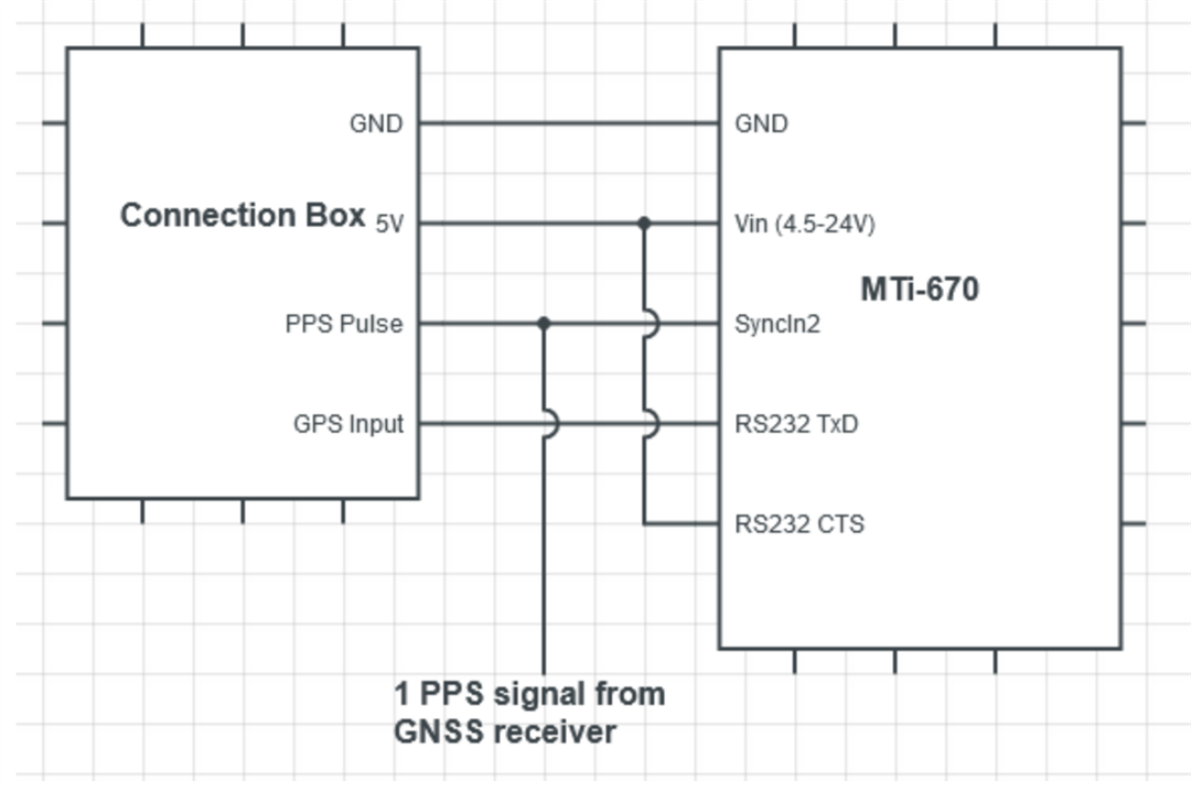
This article describes how to interface your GNSS/INS device with a HESAI Lidar. HESAI Lidars accept a GPS input which allows their data to be correlated with position. For this purpose a GPS 1PPS signal and a 1 Hz RS232 $GPRMC or $GPGGA message are required. Both the MTi-G-710 and the MTi-670 support these outputs. HESAI however does have some communication and timing constraints for external GNSS/INS devices, which can be found in the HESAI PandarXT User Manual. Most importantly the MTi needs to be configured such that it transmits the RS232 message shortly after transmitting the 1 PPS signal. This article describes how to configure your MTi in order to meet these requirements.
The two setups presented in this article have been tested using a HESAI PandarXT32 Lidar.
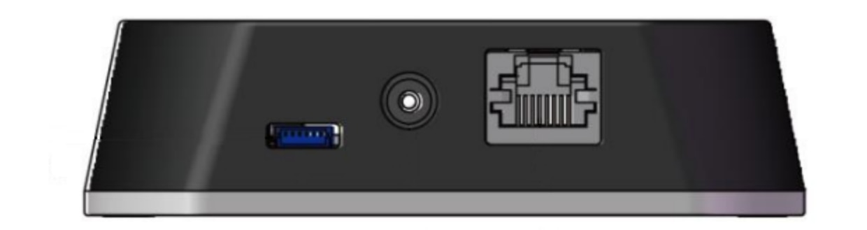
The HESAI Lidar comes with an Connection Box that includes a terminals with connections for power, GPS communication and Ethernet. In this article the connections GROUND, +5V, PPS and GPS Receive are used.


Disclaimer: In line with our RMA Terms & Conditions, the warranty on hardware devices shall be null and void if the product has been subject to improper installation. It is advised to carefully read the latest versions of the Ouster Documentation as well as the MTi product's Datasheet and Hardware Integration Manual (available here) before connecting your hardware.
This article describes how to interface your GNSS/INS device with an Ouster Lidar. Ouster Lidars accept a GPS input which allows their data to be correlated with position. For this purpose a GPS 1PPS signal and a UART $GPRMC message are required. The MTi-670/680 support these outputs. This article describes how to configure your MTi in order to meet these requirements.
The MTi-670G, MTi-680G and MTi-G-710 (encased versions with internal GNSS receiver) do not offer a 3.3V UART interface. An RS232-UART converter is required for these devices.
For more information on Ouster's sensors, please visit Ouster's website at ouster.com or contact the Sales team at lidar@ouster.io.
The setup presented in this article has been tested using an Ouster OS1 Lidar.

The Ouster Lidar comes with an Interface Box that includes a terminal with connections for Power, Ethernet, Sync, Multi Purpose, and Ground. In this article, the connections GND, SYNC_PULSE_IN, and MULTIPURPOSE_IO are used to connect to the MTi.

The circuit diagram in Figure 3 shows how to connect your MTi-670 (or MTi-680) to the Ouster Interface Box. 
On the external connector of the MTi-670/680 DK connect Pin 10 (SYNC_IN2) to the SYNC_PULSE_IN pin in the Ouster Interface Box.
On the external connector of the MTi-670/680 DK connect Pin 14 (GND) to the GND pin in the Ouster Interface Box.
On the external connector of the MTi-670/680 DK connect Pin 15 (UART_TX) to the MULTIPURPOSE_IO pin in the Ouster Interface Box.
The MTi-670/680 will need to be powered separately from the Ouster Lidar, meeting the requirements mentioned in the MTi 600-series Hardware Integration Manual. The MTi-670/680-DK can be powered by using the USB connection connected to a PC.
Ensure a good GNSS fix by testing in an area where the MTi-67/680-DK’s GNSS antenna has a clear view of the sky, so that the GNSS 1 PPS signal is available to be synced with the Ouster Lidar.
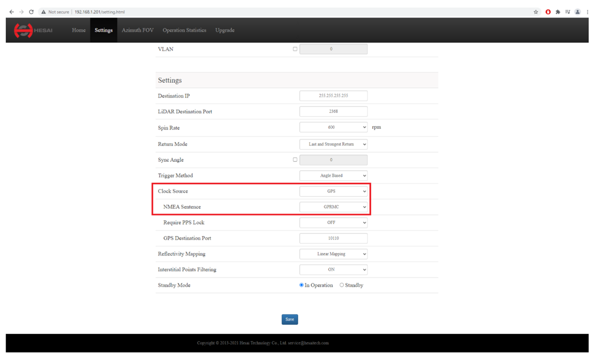
Start by configuring your MTi-670/680 to output the correct NMEA string and time data. The easiest way to do this is by using our GUI, MT Manager, which is part of the MT Software Suite.
In MT Manager, open the Device Settings window (![]() ).
).
In the Output Configuration tab, select the "String report mode" tab and enable "GPRMC". Select an output rate from the drop-down menu. Click Apply.
You may need to lower the output rate if the baud rate cannot support the selected output rate. In MT Manager this will result in data overflow warning messages shown at the bottom of the screen. At a baud rate of 115200 bps, we recommend a maximum output rate of 100 Hz. The Ouster lidar only requires data at 1 Hz.
In the Synchronization Options tab, the "Clock Bias Estimation (In)" and the "1PPS Time-pulse" features should already be present in the list of configured settings, both on line In 2.
The circuit diagram in Figure 4 shows how to connect your MTi-670G/680G to the Ouster Interface Box.

Connect the SYNC_OUT line (blue/white) of the MTi to the SYNC_PULSE_IN pin in the Ouster Interface Box. The SYNC_OUT line can also be accessed by opening up the Xsens USB converter dongle.
Connect the RS232_TxD line (yellow) of the MTi to the MULTIPURPOSE_IO pin in the Ouster Interface Box, with the RS232-UART converter in between.
Connect the RS232_CTS line (orange) of the MTi to a logical high (3V-25V), for instance to your MTi power supply line. The RS232_CTS line needs to be tied to a logical high in order to make the MTi transmit its data continuously.
The MTi-670G/680G will need to be powered separately from the Ouster Lidar, meeting the requirements mentioned in the MTi 600-series Hardware Integration Manual. The MTi-670G/680G can be powered by using the USB dongle connected to a PC.
Ensure a good GNSS fix by testing in an area where the MTi-670G/680G’s GNSS antenna has a clear view of the sky, so that the GNSS 1 PPS signal is available to the device. The MTi-670G/680G will synchronize its own clock with this trigger, and output a separate 1 PPS signal to be synced with the Ouster Lidar.
Start by configuring your MTi-670G/680G to output the correct NMEA string and time data. The easiest way to do this is by using our GUI, MT Manager, which is part of the MT Software Suite.
In MT Manager, open the Device Settings window (![]() ).
).
In the Output Configuration tab, select the "String report mode" tab and enable "GPRMC". Select an output rate from the drop-down menu. Click Apply.
You may need to lower the output rate if the baud rate cannot support the selected output rate. In MT Manager this will result in data overflow warning messages shown at the bottom of the screen. At a baud rate of 115200 bps, we recommend a maximum output rate of 100 Hz. The Ouster lidar only requires data at 1 Hz.
In the Synchronization Options tab, the "Clock Bias Estimation (In)" and the "1PPS Time-pulse" features should already be present in the list of configured settings. Click "Add", and select the Interval Transition Measurement function. Set Skip Factor to 399. Leave the other fields as is. This will create a 1 PPS signal on the SYNC_OUT line of the MTi.
Start by configuring your Ouster Lidar to receive the MTi’s sync signal and NMEA data.
If using Ouster Studio, configure the highlighted portions of Ouster Lidar’s Advanced Config as shown below:

If using TCP protocol, follow these step to configure the Ouster Lidar:
Set the timestamp_mode to TIME_FROM_SYNC_PULSE_IN- TCP command: set_config_param timestamp_mode TIME_FROM_SYNC_PULSE_IN
Set the multipurpose_io_mode to INPUT_NMEA_UART
- TCP command: set_config_param multipurpose_io_mode INPUT_NMEA_UART
Set the polarity of the sync_pulse_in pin to match the GPS PPS polarity
- TCP command: set_config_param sync_pulse_in_polarity ACTIVE_HIGH
Set the polarity of the multipurpose_io pin to match the GPS NMEA UART polarity
- TCP command: set_config_param nmea_in_polarity ACTIVE_HIGH
Set the nmea_baud_rate to match the GPS NMEA baud rate
- TCP command: set_config_param nmea_baud_rate <BAUD_11520 or BAUD_9600>
Set the nmea_leap_second to match the current leap seconds as defined by TIA at this website, at time of writing this the leap seconds are 37
- TCP command: set_config_param nmea_leap_seconds 37
Reinitialize and write the configuration
a. TCP command: reinitialize
b. TCP command: save_config_params
You can check the output from the TCP command: get_time_info
Verify that the sensor is locked onto the PPS signal
- ”sync_pulse_in": { "locked": 1
Verify that the sensor is locked on the NMEA signal
-“nmea": { “locked”: 1
Verify that last_read_message looks like a valid GPRMC sentence
- "decoding": {"last_read_message":"GPRMC,024041.00,A,5107.0017737,N,11402.3291611,W,0.080,323.3,020420,0.0,E,A*20"
Verify that timestamp time has updated to a reasonable GPS time
-"timestamp": { "time": 1585881641.96139565999999, "mode": "TIME_FROM_SYNC_PULSE_IN", "time_options": { "sync_pulse_in": 1585881641
The MTi can be configured to also output other (NMEA) string outputs when triggered by the 1 PPS signal, as long as the 9600 bps or 115200 bps baud rate allows for it. Additionally, the MTi 600-series allows for outputting data over the UART and CAN interfaces in parallel with the RS232 interface.
Disclaimer: In line with our RMA Terms & Conditions, the warranty on hardware devices shall be null and void if the product has been subject to improper installation. It is advised to carefully read the latest version of the Velodyne Interface Box Manual as well as the MTi product's Datasheet and Hardware Integration Manual (available here) before connecting your hardware.
Note: This tutorial will configure the MTi-G-710 and MTi-670/680 to output its data in response to their own GNSS 1 PPS signal. This means that the MTi will not provide any data as long as there is no valid GNSS time/position fix (except when using the CAN interface, refer to the end of this article for more details). Depending on the amount of satellites in view it can take several minutes until the 1 PPS signal is obtained by the GNSS receiver.
This article describes how to interface your GNSS/INS device with a Velodyne Lidar. Velodyne Lidars accept a GPS input which allows their data to be correlated with position. For this purpose a GNSS 1PPS signal and a 1 Hz RS232 $GPRMC or $GPGGA message are required. Both the MTi-G-710 and the MTi-670/680 support these outputs. Velodyne however does have some communication and timing constraints for external GNSS/INS devices, which can be found in the Velodyne Interface Box Manual. Most importantly the MTi needs to be configured such that it transmits the RS232 message shortly after transmitting the 1 PPS signal. This article describes how to configure your MTi in order to meet these requirements.
The MTi-670G/680G do not offer a true GNSS 1PPS, but a workaround is possible and will be discussed later in this article.
The setups presented in this article have been tested using a Velodyne VLP-16 Lidar.
The Velodyne Lidar comes with an Interface Box that includes a screw terminal with connections for power, GPS communication and Ethernet. In this article the connections GROUND, +12V, GPS PULSE and GPS RECEIVE are used.

Figure 1: Velodyne Interface Box
The circuit diagram in Figure 2 shows how to connect your MTi-G-710 to the Velodyne Interface Box.
Please note the following:

The circuit diagram in Figure 3 shows how to connect your MTi-6x0 to the Velodyne Interface Box.
Please note the following:

Figure 3: Interfacing the MTi-670/680 with the Velodyne Interface Box.
In contrast to the MTi-G-710, the MTi-6x0G does not yet offer a “true” 1 PPS output that comes straight from the internal GNSS receiver. Instead, by using the Interval Transition Measurement synchronization feature, the MTi-6x0G can be configured to generate its own 1 PPS signal that is synchronized with the 1 PPS signal of the internal receiver. This pulse will be synchronized with the internal GNSS 1 PPS pulse in terms of frequency, but not in terms of phase. This means that the 1 PPS output of the MTi-6x0G does not appear at the exact start of each UTC second. The timing of the pulse depends on the moment you power up the MTi.
The MTi-6x0G does provide sub-second data in its NMEA messages, however some lidar brands do not copy the full UTC time information from the $GPGGA or $GPRMC packets: They often assume that the 1 PPS signal and its corresponding data packet coincide with the start of a UTC second, and therefore the sub-seconds field is assumed to be zero. This can cause a data timing error of up to 1 second.
The circuit diagram in Figure 4 shows how to connect your MTi-6x0G to the Velodyne Interface Box.
Please note the following:


Xsens adds a new small form factor to its RTK GNSS/INS module, the new MTi-680 RTK GNSS/INS. This addition to the MTi 600-series brings cm-level RTK technology to the low-cost MTi 600-series module form-factor.

We are pleased to announce a new product in our MTi 600-series, expanding the choices of inertial sensor modules.
The MTi-680 supports up to centimetre position data from an external RTK GNSS receiver. As part of the MTi 600 series, this module is lightweight, rugged and cost-effective. You can seamlessly integrate the MTi-680 into your application with the header down, mount it directly to a PCB, or as a standalone, using a flat cable for communication. It is also very flexible, with native CAN support.
This new product allows for even smaller, lighter and custom designs while enabling accurate cm-level orientation and position data at high speed at an affordable price point.
The MTi-680 is great fit for applications that require data to support navigation functions, such as outdoor robotics and autonomous vehicles. These applications can be found in agriculture, last-mile deliveries, autonomous driving and driver assistance systems (ADAS), as well as outdoor construction and mining sites.
In addition, interesting markets for the MTi-680 are mapping and recording or stabilization applications. These include, for example, automotive testing, LIDAR, Sonars and USBL, gimbal/camera/platform stabilization or pedestrian navigation.
Housed in an IP51-rated plastic enclosure with dimensions of 28 mm x 31.5 mm x 13 mm, the MTi-680 is high vibration and shock-resistant. The module features a standard CAN and RS232 interfaces and an output rate of up to 400 Hz. The MTi-680 offers roll/pitch measurement accuracy of 0.2 deg RMS and heading accuracy of 0.5 deg RMS.
All modules in the MTi 600-series offer high-quality features:
Visit the MTi-680 RTK GNSS/INS product page for more information. The MTi-680 RTK GNSS/INS is part of the MTi 600-series. Find out more about it below:


