


Recently, I've decided to give flexible PCBs a go, using the prototype service available from typical PCB manufacturers.
I had my reasons, in particular, it's a great time-saver, because I don't enjoy creating custom cables for off-board connections. Sure the flexible PCB has a price, but the time saving can make up for it, especially if you intend to make more than one prototype (in my case, five will be assembled).
Another good reason is that flexible PCBs take all the strain off main PCBs, if chassis connectors/controls are attached to the flexible PCB instead of a main rigid PCB.
Thirdly, I found that it eliminated a lot of separate boards and cables; you can replace multiple boards and multiple cables with a single flexible PCB assembly.
The flexible PCBs in the photo below will ultimately form part of an antenna analyzer project; the flexible PCB will connect the rotary user controls to the main rigid PCB.

Here's how I went about it.
First off, configure the stackup in KiCad as shown in the screenshot below. It's not essential, but it will make your 3D renders look nice.

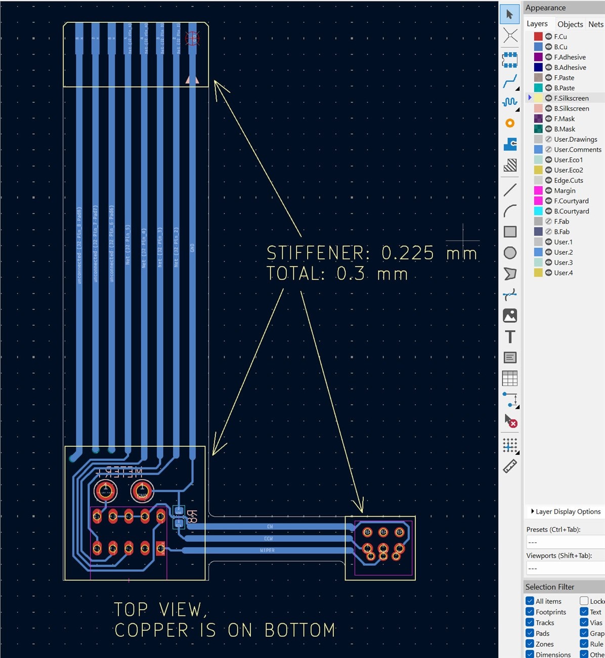
Next, create the flexible PCB design pretty much the same way as you would create any normal rigid PCB. In my case, I created a one-sided design, to save costs. You can see that I decided to create the copper tracks on the underside (blue).
I decided to dedicate the top side silkscreen layer (yellow) for board notes. The key information you need to add is some text indicating how thick you want any flex PCB stiffeners to be, and draw outlines of the stiffeners, and draw arrows indicating them very clearly.
The thickness values in the screenshot below are supported by the PCB manufacturer.
That's all you need to do in terms of layout in KiCad. You can check the 3D render to see if all is as you expect:


Once you're happy, generate your Gerber files as usual, but deselect the top copper layer if you're creating just a single layer design as I did.. You could simply remove the top layer Gerber file (and the top mask layer and any other top layers, apart from the top silkscreen which you're using as a notes layer) from the zip file bundle of Gerber files which you submit to the PCB manufacturer. You could even rename the top silkscreen layer filename if desired, but I dont' think that's essential.
Prior to completing the order, select that you want the manufacture to review the design before proceeding. This is just in case they have any questions.
Then, wait a week or two for the flexible PCBs to arrive!
The photo below shows the stiffener area at the end of the flexible PCB which will attach to the rigid PCB. You can get flat flex sockets from AliExpress, I used 2.54 mm pitch sockets that fit normal SIL header pin layouts.

The photo below shows how a rotary switch will fit onto the flexible PCB.

In terms of cost, it worked out to £3.60 per flex PCB, in a quantity of 10, including shipping. I think that's easily worth the time saving, if half a dozen or so are to be assembled.
Thanks for reading!


