element14 Community
element14 Community
    Register Log In
  • Site
  • Search
  • Log In Register
  • Community Hub
    Community Hub
    • What's New on element14
    • Feedback and Support
    • Benefits of Membership
    • Personal Blogs
    • Members Area
    • Achievement Levels
  • Learn
    Learn
    • Ask an Expert
    • eBooks
    • element14 presents
    • Learning Center
    • Tech Spotlight
    • STEM Academy
    • Webinars, Training and Events
    • Learning Groups
  • Technologies
    Technologies
    • 3D Printing
    • FPGA
    • Industrial Automation
    • Internet of Things
    • Power & Energy
    • Sensors
    • Technology Groups
  • Challenges & Projects
    Challenges & Projects
    • Design Challenges
    • element14 presents Projects
    • Project14
    • Arduino Projects
    • Raspberry Pi Projects
    • Project Groups
  • Products
    Products
    • Arduino
    • Avnet & Tria Boards Community
    • Dev Tools
    • Manufacturers
    • Multicomp Pro
    • Product Groups
    • Raspberry Pi
    • RoadTests & Reviews
  • About Us
  • Store
    Store
    • Visit Your Store
    • Choose another store...
      • Europe
      •  Austria (German)
      •  Belgium (Dutch, French)
      •  Bulgaria (Bulgarian)
      •  Czech Republic (Czech)
      •  Denmark (Danish)
      •  Estonia (Estonian)
      •  Finland (Finnish)
      •  France (French)
      •  Germany (German)
      •  Hungary (Hungarian)
      •  Ireland
      •  Israel
      •  Italy (Italian)
      •  Latvia (Latvian)
      •  
      •  Lithuania (Lithuanian)
      •  Netherlands (Dutch)
      •  Norway (Norwegian)
      •  Poland (Polish)
      •  Portugal (Portuguese)
      •  Romania (Romanian)
      •  Russia (Russian)
      •  Slovakia (Slovak)
      •  Slovenia (Slovenian)
      •  Spain (Spanish)
      •  Sweden (Swedish)
      •  Switzerland(German, French)
      •  Turkey (Turkish)
      •  United Kingdom
      • Asia Pacific
      •  Australia
      •  China
      •  Hong Kong
      •  India
      • Japan
      •  Korea (Korean)
      •  Malaysia
      •  New Zealand
      •  Philippines
      •  Singapore
      •  Taiwan
      •  Thailand (Thai)
      • Vietnam
      • Americas
      •  Brazil (Portuguese)
      •  Canada
      •  Mexico (Spanish)
      •  United States
      Can't find the country/region you're looking for? Visit our export site or find a local distributor.
  • Translate
  • Profile
  • Settings
PCB Design, Prototyping and Production
  • Products
  • More
PCB Design, Prototyping and Production
PCB Forum MP2172 step down switcher. Anyone have experience getting one going please?
  • Blog
  • Forum
  • Documents
  • Leaderboard
  • Files
  • Members
  • Mentions
  • Sub-Groups
  • Tags
  • More
  • Cancel
  • New
Join PCB Design, Prototyping and Production to participate - click to join for free!
Actions
  • Share
  • More
  • Cancel
Forum Thread Details
  • State Not Answered
  • Replies 3 replies
  • Subscribers 144 subscribers
  • Views 124 views
  • Users 0 members are here
Related

MP2172 step down switcher. Anyone have experience getting one going please?

davebullockmbe
davebullockmbe 7 days ago

Hi everyone,

I am struggling with a Monolithic Power MP2172 'buck' switching IC design.

The manufacturer's data sheet (page 15) shows a 'recommended' pcb layout but it is confusing as the picture has 'vias' that appear to be going nowhere?

image

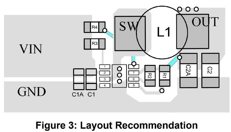
It looks as though the layout is a double sided board as there are a couple of (coloured blue) tracks that must be on the bottom.
However there are 'vias' under the IC that appear to go nowhere unless there is a ground plane or other layer?
There are also 3 'vias' at the top of the OUT copper that don't make sense either, if there is no plane beneath.
So:-
I generated my own layout which was being added to a double sided board with a top and bottom side ground plane.

image

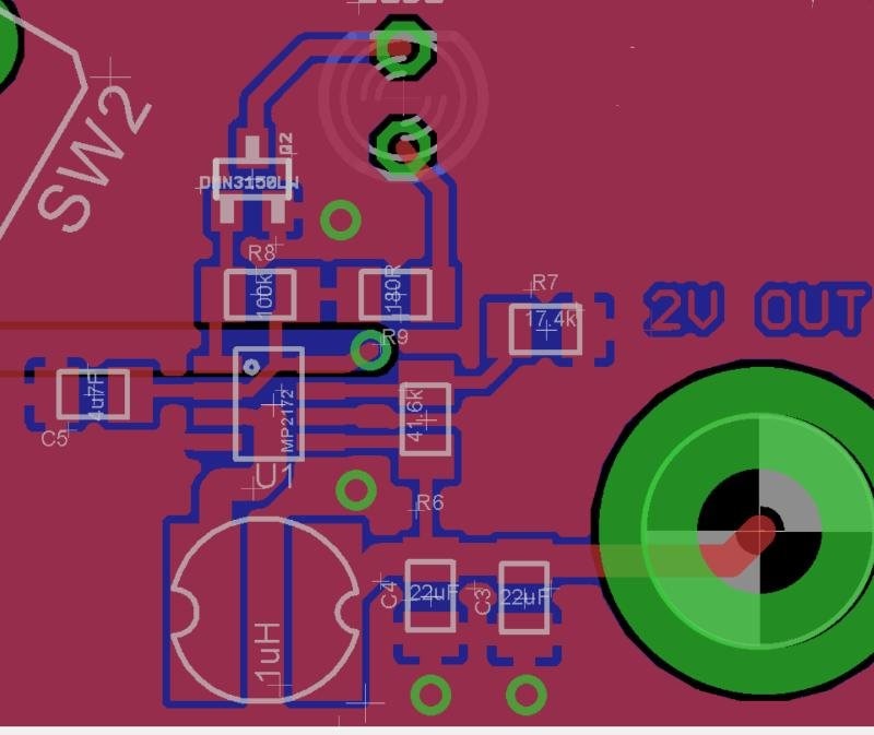
The 'switcher is to generate 2V dc from a single LiPo battery, I calculated the correct values for the FB divider and had my board made.
Sadly when populated the switching converter only produced 0.5V.
A quick 'scope around the IC found a 4 step staircase waveform on the SW pin, as though the IC was trying to start and failing.
Further investigation revealed my supply input decoupling was only 4.7uF instead of the recommended 2 x 10uF...doooh!
I replaced the capacitor with a 22uF and a 100nF in parallel which improved the situation by now producing 1.3V and a much larger 25 step staircase switching waveform.
However still not getting up to full operation.
I then tried drilling extra via holes next to the grounded end of the input decoupling capacitors and 'pinned' this point with a through wire to the GND plane on the bottom
layer, Thinking I had a high impedance GND or ground loop.
This stopped the switching completely!

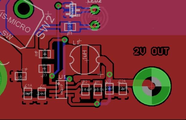
I have since reworked my layout (below) making it as close to the recommended one, and, pared back the bottom layer ground plane from beneath the switcher.
But before I get a new board made I could do with advice from someone who has experience with this family of switching IC's and in particular the MP2172.

image


Please help if you can..:-)
Thanks in anticipation

Dave

  • Sign in to reply
  • Cancel

Top Replies

  • jc2048
    jc2048 3 days ago in reply to davebullockmbe +1
    Some other things to think about. Is the inductor shielded? A semi-shielded part may give you problems here because of the field extending to the sides and down into the tracks/plane areas, particularly…
Parents
  • jc2048
    0 jc2048 4 days ago

    There's an evaluation board for the 2172 here

    https://www.monolithicpower.com/en/ev2172-j-00a.html

    That shows a layout in its datasheet.

    That's a better starting point than the snippet-of-whatever-it-is in the datasheet. The EVB operates well for sure, or they wouldn't be letting it anywhere near a customer.

    Their aims are slightly different to yours - they simply want to showcase the chip to best advantage - but they're still keeping it all fairly compact to do that, so if you understand why they're doing the things they're doing there, it will stand you in good stead for doing your own.

    • Cancel
    • Vote Up 0 Vote Down
    • Sign in to reply
    • Verify Answer
    • Cancel
  • davebullockmbe
    0 davebullockmbe 4 days ago in reply to jc2048

    HI jc2048,

    I was unaware of the datasheet on the EV Board so thank you for this.
    AS you see above I reworked my terrible layout to mimic the 'suggested layout' in the IC's original datasheet, however the EV board layout is different again with components in a completely different placements.
    Well my new board is half way through production, so lets see if it works properly. If not you have now pointed me to what should be a 'sure fire' layout on the EV Board.

    Great stuff.

    Thanks for your help.

    Dave

    • Cancel
    • Vote Up 0 Vote Down
    • Sign in to reply
    • Verify Answer
    • Cancel
  • jc2048
    0 jc2048 3 days ago in reply to davebullockmbe

    Some other things to think about.

    Is the inductor shielded? A semi-shielded part may give you problems here because of the field extending to the sides and down into the tracks/plane areas, particularly with coupling to the feedback resistors. [The usual shielded part has a small airgap for the energy storage, but they put it as a ring on the top surface, so the external part of the small fringing field points up and away from the board planes and components.]
    Is the core material good for the frequency you're running it at?
    How much headroom do you have on the saturation current (remember that this is a soft ferrite, so the saturation current gets specified at 20% down on the nominal inductance value, so you really don't want to be anywhere near that at all)?
    How did you determine the coil value? Did you use their on-line tool or do it yourself from the datasheet? If you're running from a battery, is it single cell? If so, you'll have to be very careful to look at both ends of the voltage range since that's quite a dramatic change in input voltage.

    How noisy is your load? Is it something synchronous like a processor that could be sending noise back into your converter. The COT may be prone to resetting cycles early if there are noise spikes.

    The converter self oscillates using the voltage ripple, so there needs to actually be voltage ripple clear of noise for reliable operation, so the combined ESR of the output caps is going to be a factor. The datasheet should cover that in detail. Also, if you're calculating your own voltage divider for the feedback, try and keep the loading similar to their examples, as it probably needs a minimum load to work well - don't be tempted to increase the values dramatically [if you think noise is coupling to the feedback, you could try temporarily dramatically reducing the values of the resistors to make it harder for the coupling to occur].

    I don't know that you've helped yourself with the second layout. You might have done better to experiment with the first one to determine where the problem lies - there's nothing to stop you adding wires, soldering on bits of copper foil, adding temporary shields between components, and so on.

    As to guidance for layout, look at the application notes that all the manufacturers of converter chips produce. They're as good as anything you'll find in books, and much more reliable than random people like me on the internet. But the basic principles are simple. Keep the input and output current loops as tight as possible, and keep the high dv/dt stuff away from the analogue feedback bits. Oh, and it's worth remembering that the designers of chips do think about layout issues and have in mind how the external layout is going to work, so look at the pinout and think your way back to what was going through the designer's head and why they arranged the pins in a particular way.

    • Cancel
    • Vote Up +1 Vote Down
    • Sign in to reply
    • Verify Answer
    • Cancel
Reply
  • jc2048
    0 jc2048 3 days ago in reply to davebullockmbe

    Some other things to think about.

    Is the inductor shielded? A semi-shielded part may give you problems here because of the field extending to the sides and down into the tracks/plane areas, particularly with coupling to the feedback resistors. [The usual shielded part has a small airgap for the energy storage, but they put it as a ring on the top surface, so the external part of the small fringing field points up and away from the board planes and components.]
    Is the core material good for the frequency you're running it at?
    How much headroom do you have on the saturation current (remember that this is a soft ferrite, so the saturation current gets specified at 20% down on the nominal inductance value, so you really don't want to be anywhere near that at all)?
    How did you determine the coil value? Did you use their on-line tool or do it yourself from the datasheet? If you're running from a battery, is it single cell? If so, you'll have to be very careful to look at both ends of the voltage range since that's quite a dramatic change in input voltage.

    How noisy is your load? Is it something synchronous like a processor that could be sending noise back into your converter. The COT may be prone to resetting cycles early if there are noise spikes.

    The converter self oscillates using the voltage ripple, so there needs to actually be voltage ripple clear of noise for reliable operation, so the combined ESR of the output caps is going to be a factor. The datasheet should cover that in detail. Also, if you're calculating your own voltage divider for the feedback, try and keep the loading similar to their examples, as it probably needs a minimum load to work well - don't be tempted to increase the values dramatically [if you think noise is coupling to the feedback, you could try temporarily dramatically reducing the values of the resistors to make it harder for the coupling to occur].

    I don't know that you've helped yourself with the second layout. You might have done better to experiment with the first one to determine where the problem lies - there's nothing to stop you adding wires, soldering on bits of copper foil, adding temporary shields between components, and so on.

    As to guidance for layout, look at the application notes that all the manufacturers of converter chips produce. They're as good as anything you'll find in books, and much more reliable than random people like me on the internet. But the basic principles are simple. Keep the input and output current loops as tight as possible, and keep the high dv/dt stuff away from the analogue feedback bits. Oh, and it's worth remembering that the designers of chips do think about layout issues and have in mind how the external layout is going to work, so look at the pinout and think your way back to what was going through the designer's head and why they arranged the pins in a particular way.

    • Cancel
    • Vote Up +1 Vote Down
    • Sign in to reply
    • Verify Answer
    • Cancel
Children
No Data
element14 Community

element14 is the first online community specifically for engineers. Connect with your peers and get expert answers to your questions.

  • Members
  • Learn
  • Technologies
  • Challenges & Projects
  • Products
  • Store
  • About Us
  • Feedback & Support
  • FAQs
  • Terms of Use
  • Privacy Policy
  • Legal and Copyright Notices
  • Sitemap
  • Cookies

An Avnet Company © 2026 Premier Farnell Limited. All Rights Reserved.

Premier Farnell Ltd, registered in England and Wales (no 00876412), registered office: Farnell House, Forge Lane, Leeds LS12 2NE.

ICP 备案号 10220084.

Follow element14

  • X
  • Facebook
  • linkedin
  • YouTube