element14 Community
element14 Community
    Register Log In
  • Site
  • Search
  • Log In Register
  • Community Hub
    Community Hub
    • What's New on element14
    • Feedback and Support
    • Benefits of Membership
    • Personal Blogs
    • Members Area
    • Achievement Levels
  • Learn
    Learn
    • Ask an Expert
    • eBooks
    • element14 presents
    • Learning Center
    • Tech Spotlight
    • STEM Academy
    • Webinars, Training and Events
    • Learning Groups
  • Technologies
    Technologies
    • 3D Printing
    • FPGA
    • Industrial Automation
    • Internet of Things
    • Power & Energy
    • Sensors
    • Technology Groups
  • Challenges & Projects
    Challenges & Projects
    • Design Challenges
    • element14 presents Projects
    • Project14
    • Arduino Projects
    • Raspberry Pi Projects
    • Project Groups
  • Products
    Products
    • Arduino
    • Avnet & Tria Boards Community
    • Dev Tools
    • Manufacturers
    • Multicomp Pro
    • Product Groups
    • Raspberry Pi
    • RoadTests & Reviews
  • About Us
    About the element14 Community
  • Store
    Store
    • Visit Your Store
    • Choose another store...
      • Europe
      •  Austria (German)
      •  Belgium (Dutch, French)
      •  Bulgaria (Bulgarian)
      •  Czech Republic (Czech)
      •  Denmark (Danish)
      •  Estonia (Estonian)
      •  Finland (Finnish)
      •  France (French)
      •  Germany (German)
      •  Hungary (Hungarian)
      •  Ireland
      •  Israel
      •  Italy (Italian)
      •  Latvia (Latvian)
      •  
      •  Lithuania (Lithuanian)
      •  Netherlands (Dutch)
      •  Norway (Norwegian)
      •  Poland (Polish)
      •  Portugal (Portuguese)
      •  Romania (Romanian)
      •  Russia (Russian)
      •  Slovakia (Slovak)
      •  Slovenia (Slovenian)
      •  Spain (Spanish)
      •  Sweden (Swedish)
      •  Switzerland(German, French)
      •  Turkey (Turkish)
      •  United Kingdom
      • Asia Pacific
      •  Australia
      •  China
      •  Hong Kong
      •  India
      •  Japan
      •  Korea (Korean)
      •  Malaysia
      •  New Zealand
      •  Philippines
      •  Singapore
      •  Taiwan
      •  Thailand (Thai)
      •  Vietnam
      • Americas
      •  Brazil (Portuguese)
      •  Canada
      •  Mexico (Spanish)
      •  United States
      Can't find the country/region you're looking for? Visit our export site or find a local distributor.
  • Translate
  • Profile
  • Settings
Raspberry Pi
  • Products
  • More
Raspberry Pi
Blog Pulse Train Hat for the Raspberry Pi
  • Blog
  • Forum
  • Documents
  • Quiz
  • Events
  • Polls
  • Files
  • Members
  • Mentions
  • Sub-Groups
  • Tags
  • More
  • Cancel
  • New
Join Raspberry Pi to participate - click to join for free!
Featured Articles
Announcing Pi
Technical Specifications
Raspberry Pi FAQs
Win a Pi
GPIO Pinout
Raspberry Pi Wishlist
Comparison Chart
Quiz
  • Share
  • More
  • Cancel
Group Actions
  • Group RSS
  • More
  • Cancel
Engagement
  • Author Author: pthat
  • Date Created: 14 Apr 2017 1:49 PM Date Created
  • Views 3693 views
  • Likes 1 like
  • Comments 14 comments
Related
Recommended
  • pthat
  • raspberry pi
  • pulse train hat
  • dds generators
  • pulse train
  • raspberry pi hat

Pulse Train Hat for the Raspberry Pi

pthat
pthat
14 Apr 2017

I am hoping that a new HAT we have designed and released will be of interest to anyone wanting to control motors within their own projects using the Raspberry Pi computer.

image

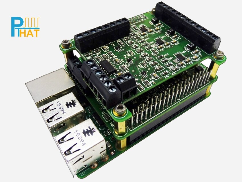
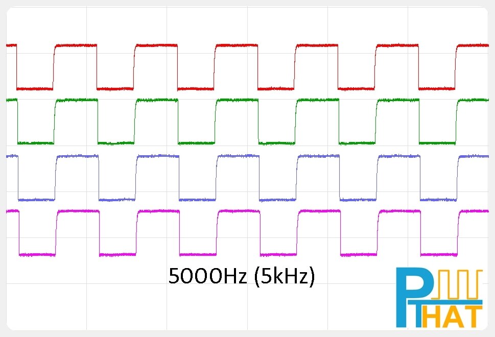
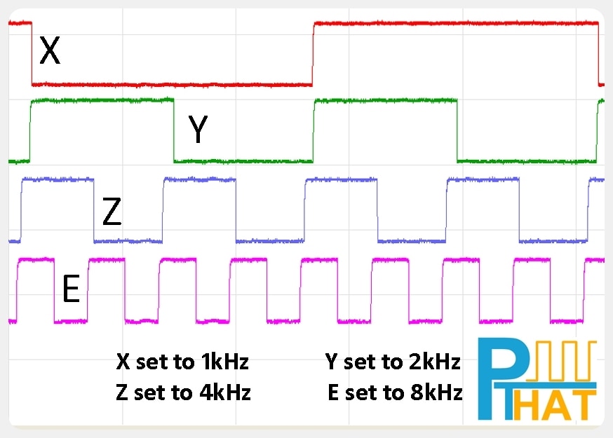
The Pulse Train Hat is an add-on board for the Rapsberry Pi computer and allows clean, fast and accurate pulses to be created using simple ASCII commands.


There are many hardware designs where a variable frequency pulse is needed, but one that is the most popular is for driving stepper/servo motors that use pulse and direction lines.

Motors like this are found in machines such as 3D Printers, CNC machines, Robot Arms and not to mention the other endless motion control and automation machines.


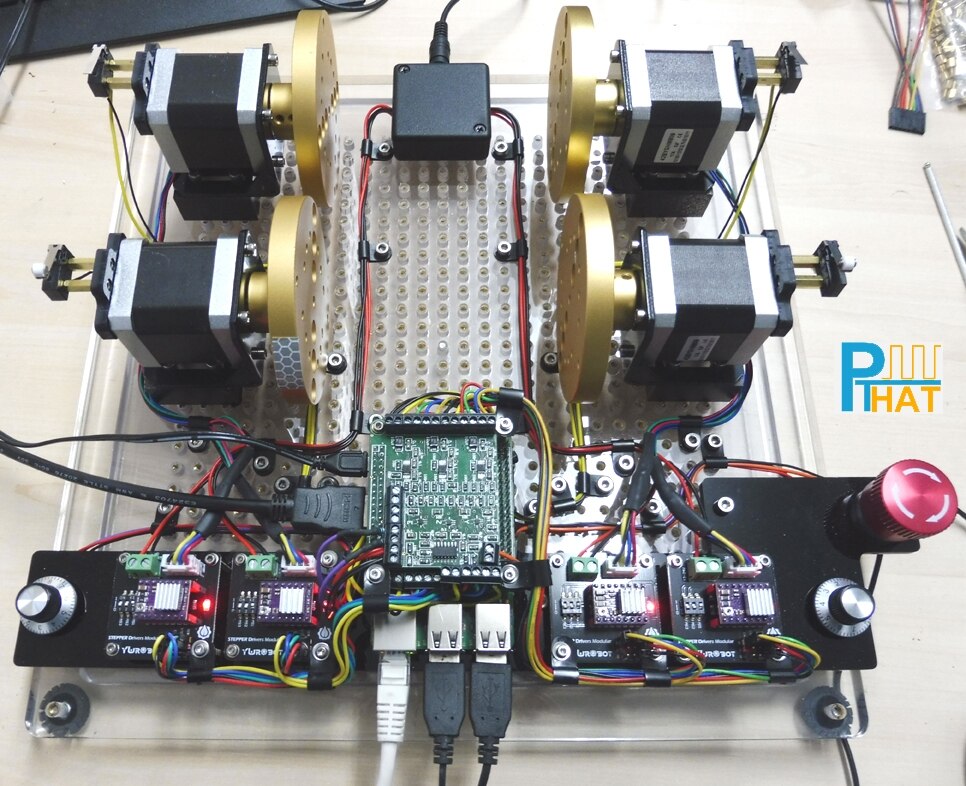
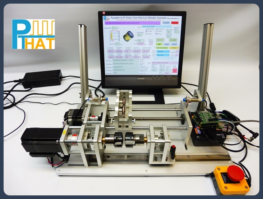
Below is a Test Rig we used while developing the code.


It allows us to test all 4 channels of the PTHAT by sending the pulses to stepper drivers, that were connected to small Nema 17 motors. It also has all the limit switch inputs brought out to switches, the ADC inputs connect to 10K pots and AUX outputs connected to LED’s.


We decided to use low cost stepper drivers that are usually found in 3D printers as they are not brilliant, but do the job. Our thinking is if the PTHAT can control these noisy little drivers, then handling the more expensive drivers would be easier!


image


Controlling motors may seem simple, but when you get down to detailed control, it can all become very confusing and a big learning curve.


With the new Pulse Train Hat (PTHAT) add-on for the Raspberry Pi and a new dedicated support site http://www.pthat.com , we plan to make that task very simple and allow everyone to easily create their automation product.


image


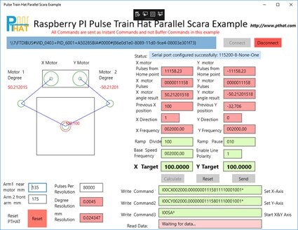
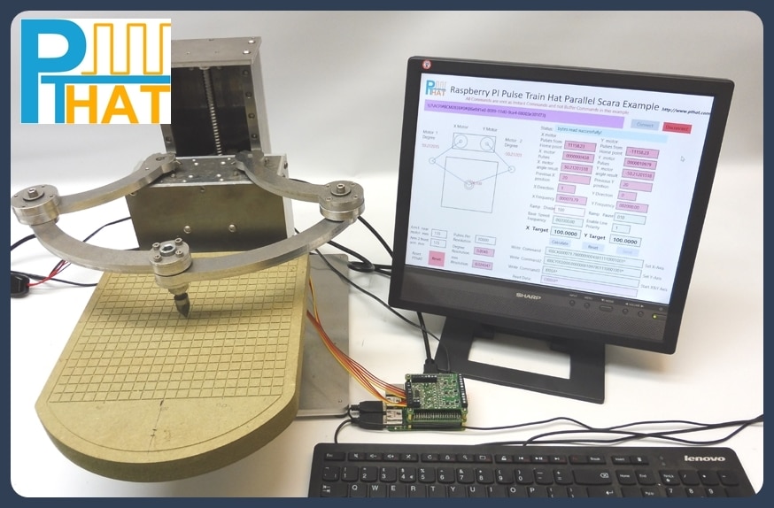
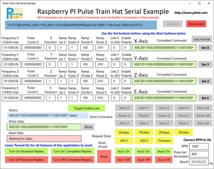
We have created an number of example applications using Visual Studio 2015 that can be used with Windows 10 IOT.

These examples have been written in C# as a Universal Windows Platform (UWP) and all the source code can be downloaded from the website.


image

image


image

image

image


We have also designed the PTHAT to have it's firmware upgraded easily using a JTAG programmer that we supply with each board.

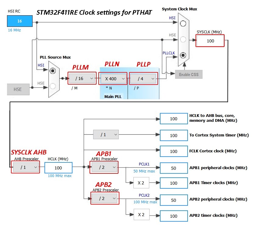
Also full details on the ARM processor we use has been released covering all the GPIO information, Clock settings and peripherals for people wanting to write their own firmware.


image


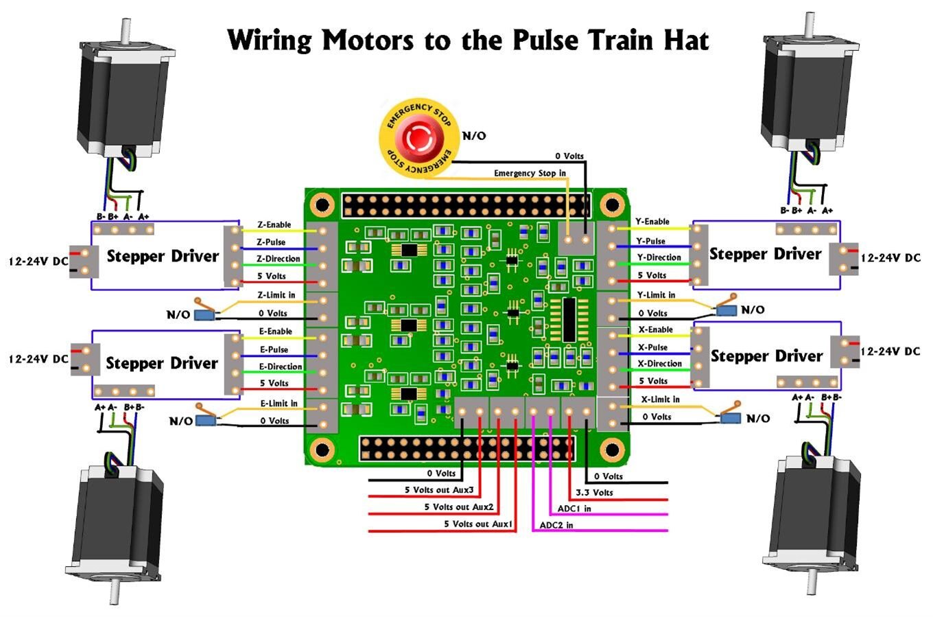
Also there are a number of wiring diagrams released covering various stepper driver hook ups.

image

Of course you do not have to use the PTHAT to control motors and can be used as a pulse generator for other projects.


image


image


Please feel free to check out the dedicated support site for more information http://www.pthat.com

  • Sign in to reply

Top Comments

  • pthat
    pthat over 8 years ago +4
    Yep most of controllers out there accept raw Gcode commands and do all the calculations in firmware, including G01 Linear interpolation commands and G02 Circular interpolation commands. So software like…
  • pthat
    pthat over 8 years ago +3
    There are already a lot of dedicated controllers out there for CNC machines and 3D printers etc, that are used as either dedicated toolpath engines, accepting Gcode and they work well. The Pulse Train…
  • Robert Peter Oakes
    Robert Peter Oakes over 8 years ago in reply to pthat +3
    Thanks for the prompt response, checking the specifications of the CPU, looks like it would be more than able to take a port from any of the Arduino based GCode engines and provide a better performance…
  • Robert Peter Oakes
    Robert Peter Oakes over 8 years ago in reply to pthat

    Thanks for the prompt response, checking the specifications of the CPU, looks like it would be more than able to take a port from any of the Arduino based GCode engines and provide a better performance afterwards too. Lest see if someone takes up the challenge. image

    • Cancel
    • Vote Up +3 Vote Down
    • Sign in to reply
    • More
    • Cancel
  • pthat
    pthat over 8 years ago

    There are already a lot of dedicated controllers out there for CNC machines and 3D printers etc, that are used as either dedicated toolpath engines, accepting Gcode and they work well.

    The Pulse Train Hat is a development board to allow people to control motors in all different kinds of ways, including CNC machines if they want to write the software or even the firmware for it.

    But we did not want to restrict people to just using Gcode commands, as these have to be buffered and executed one command at a time.

    With the pulse train hat, all 4 pulse train outputs can be controlled individually, so you can set one motor off doing a task and at any time set off a second motor and so on, which is great for a lot of robotic applications. Also they can be set off at the same time and synchronised for interpolation with each other, like a CNC machine requires.

    In saying that we have been working on a raw buffer command set that we will release in a future version of the firmware which will buffer lots of small movement commands.

    Most of the controllers based on the Atmel family of processors use the Bresenham algorithm approach to keep interpolation between each Axis. The PTHAT takes a different approach in that it has dedicated DDS Pulse Generators that can have their frequency changed on the fly rather than calculating pulses to form an approximation of a straight line between two points.

    For advanced users that want to write firmware for a dedicated CNC controller, we have supplied all the processor configuration on the firmware page.

    http://pthat.com/index.php/firmware/

    The ARM processor we use on the PTHAT mainboard is the  STM32F411RE clocked at 100MHz, if you want to compare against the Atmel processors.

    http://www.st.com/en/microcontrollers/stm32f411re.html

    • Cancel
    • Vote Up +3 Vote Down
    • Sign in to reply
    • More
    • Cancel
  • Robert Peter Oakes
    Robert Peter Oakes over 8 years ago

    How well could this handle GCODE or something similar where the co-ordination of 4 axis are needed in cutting arcs or other multi axis features (Sculpturing for instance). this requires either asking the controller directly to drive the steppers in the required arc or having the host interpret that arc into a very large number of small step and direction commands but keeping the movement smooth enough to not leave artifacts from cutting or laying down filament etc.


    is there enough FLASH and RAM space to do this. In comparison...

    An Arduino UNO is able to handle 3 axis G Code very well from a serial data stream and includes direct interpretation of arcs etc.,

    Upgrade to an ATMEGA and it can handle 4 or more axis (Mainly due to more IO pins but the RM and FLASH increase helps too of course.)


    What I am trying to see is what this brings to the table that a UNO connected through the serial port does not offer with an off the shelf daughter board to carry the drivers, the PI provides the master control in both cases. the HAT/Serially connected board interprets the G Code or other format commands. So far all i'm seeing is an equivilent to an OctoPI with something like an UNO with a driver board., just with a different MPU and not embedded driver support ?


    I actually dont have an issue with using separate drivers by the way, it adds more flexibility to the solution. my references are for comparison only.

    • Cancel
    • Vote Up 0 Vote Down
    • Sign in to reply
    • More
    • Cancel
  • pthat
    pthat over 8 years ago in reply to dougw

    I think Doug is asking if it can do PWM and allow the user to vary the pulse width/duty cycle like you would control a DC motor, the wider the pulse the more current flows and hence speed of motor increases.

    This is a common way to drive DC motors and there are lots of controller cards out there already that do this. Great for speed but without a encoder on the back, using it for accuracy can be difficult.


    The PTHAT does not allow you to alter the duty cycle and it is designed to give a variable frequency output of the pulse train.

    The pulse train gets fed into stepper/servo motor drivers that have inputs for the Pulse, Step and Direction lines.

    This is a more accurate as you are controlling the motor down to very small degrees and have very accurate movement.

    So the faster you send the pulses to the driver, the faster the motor will spin.


    There are a number of timers on the STM32F411RE processor we use on board that can be used as PWM outputs and where you can vary the duty cycle. So anyone writing their own firmware could use these or maybe it is something we would add to the existing firmware if the demand was enough.


    Cheers


    Sean

    • Cancel
    • Vote Up +2 Vote Down
    • Sign in to reply
    • More
    • Cancel
  • balearicdynamics
    balearicdynamics over 8 years ago in reply to dougw

    I think yes and can say more. This accessory is very good as they though to most (maybe all) the needs that can arise in motor control putting the user at a high level interface while the dirty work is done by the board. In all the sample circuits (and photos) I see that the only extra boards are the power units for the motors.


    According with the ASCII command set specifications you can see that they have provided not only the useful emergency stop but also considered limiting switches, auto direction and more. You can find the entire command set here: http://pthat.com/index.php/command-set/


    Seeing the example page here Examples | Pulse Train Hat I tend to consider trustable this point of view as well as seeing the test videos shown on the their site.


    in the motor information page http://pthat.com/index.php/motor-information/ again it is explained that just the stepper controller should be added (half bridges, as a matter of fact) while the job is done by the HAT. Maybe I have missed some detail but I think that the best solution is to try it doing some experiments image


    At last, this page sounds a revelation image http://pthat.com/index.php/wiring-up/


    Enrico

    • Cancel
    • Vote Up +1 Vote Down
    • Sign in to reply
    • More
    • Cancel
<>
element14 Community

element14 is the first online community specifically for engineers. Connect with your peers and get expert answers to your questions.

  • Members
  • Learn
  • Technologies
  • Challenges & Projects
  • Products
  • Store
  • About Us
  • Feedback & Support
  • FAQs
  • Terms of Use
  • Privacy Policy
  • Legal and Copyright Notices
  • Sitemap
  • Cookies

An Avnet Company © 2026 Premier Farnell Limited. All Rights Reserved.

Premier Farnell Ltd, registered in England and Wales (no 00876412), registered office: Farnell House, Forge Lane, Leeds LS12 2NE.

ICP 备案号 10220084.

Follow element14

  • X
  • Facebook
  • linkedin
  • YouTube