element14 Community
element14 Community
    Register Log In
  • Site
  • Search
  • Log In Register
  • About Us
  • Community Hub
    Community Hub
    • What's New on element14
    • Feedback and Support
    • Benefits of Membership
    • Personal Blogs
    • Members Area
    • Achievement Levels
  • Learn
    Learn
    • Ask an Expert
    • eBooks
    • element14 presents
    • Learning Center
    • Tech Spotlight
    • STEM Academy
    • Webinars, Training and Events
    • Learning Groups
  • Technologies
    Technologies
    • 3D Printing
    • FPGA
    • Industrial Automation
    • Internet of Things
    • Power & Energy
    • Sensors
    • Technology Groups
  • Challenges & Projects
    Challenges & Projects
    • Design Challenges
    • element14 presents Projects
    • Project14
    • Arduino Projects
    • Raspberry Pi Projects
    • Project Groups
  • Products
    Products
    • Arduino
    • Avnet Boards Community
    • Dev Tools
    • Manufacturers
    • Multicomp Pro
    • Product Groups
    • Raspberry Pi
    • RoadTests & Reviews
  • Store
    Store
    • Visit Your Store
    • Choose another store...
      • Europe
      •  Austria (German)
      •  Belgium (Dutch, French)
      •  Bulgaria (Bulgarian)
      •  Czech Republic (Czech)
      •  Denmark (Danish)
      •  Estonia (Estonian)
      •  Finland (Finnish)
      •  France (French)
      •  Germany (German)
      •  Hungary (Hungarian)
      •  Ireland
      •  Israel
      •  Italy (Italian)
      •  Latvia (Latvian)
      •  
      •  Lithuania (Lithuanian)
      •  Netherlands (Dutch)
      •  Norway (Norwegian)
      •  Poland (Polish)
      •  Portugal (Portuguese)
      •  Romania (Romanian)
      •  Russia (Russian)
      •  Slovakia (Slovak)
      •  Slovenia (Slovenian)
      •  Spain (Spanish)
      •  Sweden (Swedish)
      •  Switzerland(German, French)
      •  Turkey (Turkish)
      •  United Kingdom
      • Asia Pacific
      •  Australia
      •  China
      •  Hong Kong
      •  India
      •  Korea (Korean)
      •  Malaysia
      •  New Zealand
      •  Philippines
      •  Singapore
      •  Taiwan
      •  Thailand (Thai)
      • Americas
      •  Brazil (Portuguese)
      •  Canada
      •  Mexico (Spanish)
      •  United States
      Can't find the country/region you're looking for? Visit our export site or find a local distributor.
  • Translate
  • Profile
  • Settings
Raspberry Pi
  • Products
  • More
Raspberry Pi
Raspberry Pi Forum RG1 1.8v regulator
  • Blog
  • Forum
  • Documents
  • Quiz
  • Events
  • Polls
  • Files
  • Members
  • Mentions
  • Sub-Groups
  • Tags
  • More
  • Cancel
  • New
Join Raspberry Pi to participate - click to join for free!
Featured Articles
Announcing Pi
Technical Specifications
Raspberry Pi FAQs
Win a Pi
Raspberry Pi Wishlist
Actions
  • Share
  • More
  • Cancel
Forum Thread Details
  • Replies 231 replies
  • Subscribers 668 subscribers
  • Views 26756 views
  • Users 0 members are here
Related

RG1 1.8v regulator

Former Member
Former Member over 13 years ago

Ok, so in a different thread I threatened to remove RG1 and do some current measurements on it's output after seeing those thermal images that show it's not generating any heat...


Well, I did it tonight. Some photos here: https://picasaweb.google.com/selsinork/RPi18v


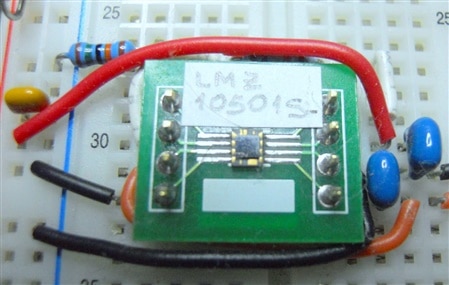
The jumper pins in the output let me either just put a jumper on and verify the Pi boots ok, or wire a multimeter in series to get some current readings.


The results were interesting to say the least. I had to go back and check I was reading the multimeter correctly, that it wasn't broken etc.


On initial power up I see a negative current for a second or so which then reverses to about 0.5mA (yes half a milliamp, that's not a typo) for a few seconds while we get the first sd-card accesses. Once we're booted and sitting at the login prompt the current reading fluctuates from around 0.001mA to maybe 0.04mA. 


I'm using the 40mA range on a decent Fluke multimeter, so I've no reason to doubt the results. There's obviously going to be some inaccuracy down at that level due to length of meter leads etc, but the result is fairly clear.  You'll understand why I was checking the meter was working and I was reading it correctly though image


So from there onto the next test, lets try completely disconnecting RG1 and see if the Pi boots while using the LAN9512 1.8v 'output'.  Yes it does! 


I think that's reasonably good indication that jamodio got it spot on, the lan9512 shouldn't be connected to the 1.8v plane and it's heat problems are going to be largely due to supplying current on it's 1.8v filter pin that it was never designed to do.


So anyone willing to pull RG1 off a Pi and verify my results ?

  • Sign in to reply
  • Cancel
Parents
  • Former Member
    Former Member over 13 years ago

    Hi guys


    As promised, I have now finished testing and it toke alot more work then i had expected but here is a blog post with all the details


    http://www.tooms.dk/Tblog/Showblog1.asp?BlogID=201208292042561198


    So now the hunt for a LDO replacement


    Hope you like it.


    Thomas


    • Cancel
    • Vote Up +1 Vote Down
    • Sign in to reply
    • Cancel
  • Former Member
    Former Member over 13 years ago in reply to Former Member

    Thomas Johansen wrote:


    Hi guys


    As promised, I have now finished testing and it toke alot more work then i had expected but here is a blog post with all the details


    http://www.tooms.dk/Tblog/Showblog1.asp?BlogID=201208292042561198


    So now the hunt for a LDO replacement


    Hope you like it.


    Thomas


    Hi


    just to say that i have now posted a follow up blog post to this with the new version 2 board


    http://www.tooms.dk/Tblog/Showblog1.asp?BlogID=201209222223022628


    Tooms

    • Cancel
    • Vote Up +2 Vote Down
    • Sign in to reply
    • Cancel
  • Former Member
    Former Member over 13 years ago in reply to Former Member

    Thanks for that Tooms, I was just thinking about trying to get hold of a v2 to repeat some of my earlier measurements.


    From your thermal images it certainly seems that the next target is to replace RG2 with some form of switching regulator.

    • Cancel
    • Vote Up 0 Vote Down
    • Sign in to reply
    • Cancel
  • Former Member
    Former Member over 13 years ago in reply to Former Member

    Hi


    yes i am working on getting an replacement for the RG1 and RG2 and maybe the RG3.


    but as i write i have still not found a good one but i am in the process of testing the TI mano switchmode modules but this is an 8 pin QFN chip therer is 2x3mm in size and i have not done so small smd things before so it will take some time and i hope it as good as they say it is, but time will tell...  i have got the boards (they are 14.4x9.3mm) and i am in the process of mounting the parts.


    Tooms

    • Cancel
    • Vote Up 0 Vote Down
    • Sign in to reply
    • Cancel
  • jamodio
    jamodio over 13 years ago in reply to Former Member

    Great article Toom, thanks for sharing.


    As I mentioned before, my opinion is that the entire power architecture has to be redesigned for the Rpi, the idea of using phone chargers with micro USB was not a good one and it is the source of many many problems and frustration, it also leaves out other and better ways to power the board.


    What switching regulators are you looking at ?  TI has a very nice and vast line of them, particularly the SWIFT ones are highly efficient.


    I had very good results with this tiny one from TI (actually an original National part later acquired by TI) which switches from 5V to 3.3V and can handle up to 1A, it is QFN and has the inductor incorporated on the chip (soldering and rework has to be done carefully to avoid removing it)

    http://www.ti.com/product/lmz10501


    Here is a pic of one mounted on a SMT to DIP adapter for testing (not the best or recommended pcb layout, but it worked).

    image


    One alternative I'm using on other designs is the ISL9104 from Intersil, it is high efficiency with low Iq running at 4.3MHz, so the inductor is just a small ferrite bead. Up to 500mA.

    http://www.intersil.com/en/products/power-management/switching-regulators/integrated-fet-regulators/ISL9104.html

    Here is a pic of a small evaluation board:

    image


    For the main power input I decided to get rid of the idea of using a USB charger and the microUSB connector and power the Rpi directly via the P1 header bypassing the main polyfuse. Then for the main 5V I'm using a SWIFT switcher from TI which I had very good results on several commercial products, the TPS54231 (http://www.ti.com/product/tps54231), I can feed up to 28V and can provide up to 2A, output voltage is adjustable via a pair of resistors. Here is a pic of a quick prototype board I put together to power the Rpi with it (at the right there is a 3.3V LDO to feed power to the extra parts on the protoboard and not drain power from the Rpi).

    image


    Let me know what part you have in mind, I can easily get samples and eval kits from TI or other vendors.


    Cheers

    Jorge

    • Cancel
    • Vote Up 0 Vote Down
    • Sign in to reply
    • Cancel
  • Former Member
    Former Member over 13 years ago in reply to jamodio

    jamodio wrote:


    Great article Toom, thanks for sharing.


    As I mentioned before, my opinion is that the entire power architecture has to be redesigned for the Rpi, the idea of using phone chargers with micro USB was not a good one and it is the source of many many problems and frustration, it also leaves out other and better ways to power the board.


    What switching regulators are you looking at ?  TI has a very nice and vast line of them, particularly the SWIFT ones are highly efficient.


    I had very good results with this tiny one from TI (actually an original National part later acquired by TI) which switches from 5V to 3.3V and can handle up to 1A, it is QFN and has the inductor incorporated on the chip (soldering and rework has to be done carefully to avoid removing it)

    http://www.ti.com/product/lmz10501


    Here is a pic of one mounted on a SMT to DIP adapter for testing (not the best or recommended pcb layout, but it worked).

    image


    One alternative I'm using on other designs is the ISL9104 from Intersil, it is high efficiency with low Iq running at 4.3MHz, so the inductor is just a small ferrite bead. Up to 500mA.

    http://www.intersil.com/en/products/power-management/switching-regulators/integrated-fet-regulators/ISL9104.html

    Here is a pic of a small evaluation board:

    image


    For the main power input I decided to get rid of the idea of using a USB charger and the microUSB connector and power the Rpi directly via the P1 header bypassing the main polyfuse. Then for the main 5V I'm using a SWIFT switcher from TI which I had very good results on several commercial products, the TPS54231 (http://www.ti.com/product/tps54231), I can feed up to 28V and can provide up to 2A, output voltage is adjustable via a pair of resistors. Here is a pic of a quick prototype board I put together to power the Rpi with it (at the right there is a 3.3V LDO to feed power to the extra parts on the protoboard and not drain power from the Rpi).

    image


    Let me know what part you have in mind, I can easily get samples and eval kits from TI or other vendors.


    Cheers

    Jorge


    Hi


    yes your spot on, it is the LMZ10501 that i am trying to use and i have now got one of them mounted on my boards.

    it is set for 3.3V ouput with the resisitors as per the PDF files but i am getting 3.27V so i guess that i have to change the values abit so i can get it a little higher.


    here is an analyze of my module (it is in microsoft xps format as i dont has a pdf writer installed)

    http://www.tooms.dk/Download/element14forum/raspi/LMZ10501-3.3V-V1.20120923.1652.xps


    as you can see it is first hitting 90% eff. at 100mA and seems to top with 93,9% at 260mA, but it is alot better then the LDO.


    Now i just need to build an 1.8V and 2.5V board and then do testing with the RPI board.


    If you have so easy access to the parts then i will love get a couple extra of the LMZ10501 as i only have a couple of them via the sample service and maybe 3 Intersil so i can set one to 3.3V and 1.8V and the last to 2.5V


    Thanks

    Thomas

    • Cancel
    • Vote Up 0 Vote Down
    • Sign in to reply
    • Cancel
Reply
  • Former Member
    Former Member over 13 years ago in reply to jamodio

    jamodio wrote:


    Great article Toom, thanks for sharing.


    As I mentioned before, my opinion is that the entire power architecture has to be redesigned for the Rpi, the idea of using phone chargers with micro USB was not a good one and it is the source of many many problems and frustration, it also leaves out other and better ways to power the board.


    What switching regulators are you looking at ?  TI has a very nice and vast line of them, particularly the SWIFT ones are highly efficient.


    I had very good results with this tiny one from TI (actually an original National part later acquired by TI) which switches from 5V to 3.3V and can handle up to 1A, it is QFN and has the inductor incorporated on the chip (soldering and rework has to be done carefully to avoid removing it)

    http://www.ti.com/product/lmz10501


    Here is a pic of one mounted on a SMT to DIP adapter for testing (not the best or recommended pcb layout, but it worked).

    image


    One alternative I'm using on other designs is the ISL9104 from Intersil, it is high efficiency with low Iq running at 4.3MHz, so the inductor is just a small ferrite bead. Up to 500mA.

    http://www.intersil.com/en/products/power-management/switching-regulators/integrated-fet-regulators/ISL9104.html

    Here is a pic of a small evaluation board:

    image


    For the main power input I decided to get rid of the idea of using a USB charger and the microUSB connector and power the Rpi directly via the P1 header bypassing the main polyfuse. Then for the main 5V I'm using a SWIFT switcher from TI which I had very good results on several commercial products, the TPS54231 (http://www.ti.com/product/tps54231), I can feed up to 28V and can provide up to 2A, output voltage is adjustable via a pair of resistors. Here is a pic of a quick prototype board I put together to power the Rpi with it (at the right there is a 3.3V LDO to feed power to the extra parts on the protoboard and not drain power from the Rpi).

    image


    Let me know what part you have in mind, I can easily get samples and eval kits from TI or other vendors.


    Cheers

    Jorge


    Hi


    yes your spot on, it is the LMZ10501 that i am trying to use and i have now got one of them mounted on my boards.

    it is set for 3.3V ouput with the resisitors as per the PDF files but i am getting 3.27V so i guess that i have to change the values abit so i can get it a little higher.


    here is an analyze of my module (it is in microsoft xps format as i dont has a pdf writer installed)

    http://www.tooms.dk/Download/element14forum/raspi/LMZ10501-3.3V-V1.20120923.1652.xps


    as you can see it is first hitting 90% eff. at 100mA and seems to top with 93,9% at 260mA, but it is alot better then the LDO.


    Now i just need to build an 1.8V and 2.5V board and then do testing with the RPI board.


    If you have so easy access to the parts then i will love get a couple extra of the LMZ10501 as i only have a couple of them via the sample service and maybe 3 Intersil so i can set one to 3.3V and 1.8V and the last to 2.5V


    Thanks

    Thomas

    • Cancel
    • Vote Up 0 Vote Down
    • Sign in to reply
    • Cancel
Children
  • Former Member
    Former Member over 13 years ago in reply to Former Member

    Tooms wrote:


    Now i just need to build an 1.8V and 2.5V board and then do testing with the RPI board.

    personally I'd not bother with the 2.5v one, going by the schematics it's only used for the composite video and doesn't look like it'll ever have significant current requirements, so an LDO will be fine.

    • Cancel
    • Vote Up 0 Vote Down
    • Sign in to reply
    • Cancel
  • Former Member
    Former Member over 13 years ago in reply to Former Member

    selsinork wrote:


    Tooms wrote:


    Now i just need to build an 1.8V and 2.5V board and then do testing with the RPI board.

    personally I'd not bother with the 2.5v one, going by the schematics it's only used for the composite video and doesn't look like it'll ever have significant current requirements, so an LDO will be fine.


    yes your right, there is no point in the 2.5V


    Tooms

    • Cancel
    • Vote Up 0 Vote Down
    • Sign in to reply
    • Cancel
element14 Community

element14 is the first online community specifically for engineers. Connect with your peers and get expert answers to your questions.

  • Members
  • Learn
  • Technologies
  • Challenges & Projects
  • Products
  • Store
  • About Us
  • Feedback & Support
  • FAQs
  • Terms of Use
  • Privacy Policy
  • Legal and Copyright Notices
  • Sitemap
  • Cookies

An Avnet Company © 2025 Premier Farnell Limited. All Rights Reserved.

Premier Farnell Ltd, registered in England and Wales (no 00876412), registered office: Farnell House, Forge Lane, Leeds LS12 2NE.

ICP 备案号 10220084.

Follow element14

  • X
  • Facebook
  • linkedin
  • YouTube