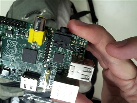
jbeale wrote:I just received my 2nd R-Pi, this one from stock (yay MCM Electronics) which took just a week to ship from Ohio to California. I was pleased, but surprised to see that the USB fuses F1, F2 are now just 0-ohm jumpers (photo below). I was able to confirm they measure less than 0.1 ohms. Is this the new standard going forward?
You've obviously recieved a Chinese pirate copy - it won't have all the features a proper Pi would have, such as not working with some keyboards, and the like.
Yes. After seeing how many people have decided to modify their boards with zero-ohm links, and having done some safety and reliability testing, we've decided that the best course of action is to remove the USB fuses from the design. Right now they're linked out, but on a subsequent board revision the pads will be removed entirely.
From Me Peg: Unlike on this Forum, I do not read every little thing on the org forum. . . BUT . . . is it just me or does this seem kind of sneaky? Or to put it another way. . . what happened to the "Open" in the open software/hardware world? Or did I miss the instructions on what to do with the two pi's I now own to make them more stable? No suggestions on buying the beagleboard Morgaine!
Thanks for the heads up on the 0-ohm change. Someone at my hackerspace Pi meetup last night told me he got his Pi from MCM last week, so I asked I could see it... and it was indeed "ohmless":
I'm very interested to see at a future meeting what will happen when we swap his Pi into someone's setup who is having trouble with USB devices that might be power related. With the USB host port polyfuses gone, I'm wondering if it is still be necessary to recommend using a self-powered hub for a WiFi adapter. (the GWU625 I've been using lists "Transmit : < 380mA. ; Receive: < 250mA").
For the polyfuse on the micro usb power input, I see on the eLinux wiki it is 1.1A with a hold current of 700mA. Does that mean the Pi can only draw 700mA before the polyfuse starts to gain resistance and decrease the 5V input?
I'm guessing the downside to 0-ohm or bigger 500mA polyfuse is that the USB devices can now draw enough current to make the power input polyfuse react. I wonder if this would effect the functioning off the rest of the Pi (which I think it using 3.3V and 1.8V rails, right?). Hookup an external harddisk directly and the Pi reboots?
> Hookup an external harddisk directly and the Pi reboots?
We don't really know what the future plans are for power distribution. Morgaine has advocated that the USB power shouldn't go through F3. Some people have suggested 1 ohm instead of zero, or larger capacitors, in order to prevent voltage sags from hot plugged USB devices. Anyway, this change seems like an improvement, even if it doesn't solve all the power issues.
I can't remember if there is an specific value required/recommended by the USB 2.0 standard, I've been usnig 150µF and the reference design schematics and eval board for the SMSC LAN9512 show that value as well for each port.
The R-Pi has a single 47µF shared by both ports.
PS. I"m still waiting to see what else is on "Pete's list", this "silent" fix by RPF replacing the polyfuses by a 0 ohm resistor is another engineering oddity and it does not sound professional that they decided to do it (and apparently testing it) because we were doing it, they should have a more reasonable explanation.
I just love it how the fanboys on the original forum praise the modification that makes their Pi even the more perfect design.
Using one capacitor for both usb ports (but with a sufficient value) shouldn't work much different than using a capacitor for each port. It will have a bit higher ESR, but it's not there to continuously flatten ripple voltages.
A bigger capacitor is a more expensive component, and we all know how hard it is to keep the low price for the board.
The camera and dsi connector make me wonder if education is really the goal of the foundition, or if that is just a fog screen to rectify the 'non profit' nature of the foundation? They missed the start of the 2012 - 2013 schoolyear. Their low price setting is great, but for a workable classroom setup, you need to add the price of a monitor, a keyboard, a mouse, a hub and a housing. The board on it's own is just part of the setup. So the only benefit compared to a netbook or cheap tablet is the fact that students can go back to basics, except, that such requires an open approach upon hardware an software? Maybe they can learn how to do reverse engineering of the binary blob. It will give them great job opportunities later on in chinese cloning factories. Altough I hope no one tries to clone the synoptics otg usb stack.
I suppose that the polyfuse fix is a "pragmatic engineering solution" - it's a low cost item and a board fix just for the USB power problem is hard to justify (especially when a fix for the 1V8 issue may be in the pipeline). The important thing is that possible caveats regarding total power draw are written large by the Foundation and not hidden under a rock, as previously happened. Similarly, I don't see why the "upgrade" to zero ohm resistors was kept quiet. While the specsheet for just about every bit of hardware typically contains wording like "specifications liable to change without notice", this is just a disclaimer, not an obligation!
I guess that the Foundation were worried about threads along the lines of "Boo-hoo, if I'd known about an upcoming upgrade I'd have delayed my purchase..."
@Luc Cool: I was a little taken aback by the announcement of the camera as the first addon (not including the Gertboard, of course). When I first became aware of the Pi (and it's educational leanings) last year I imagined that it may mature into a lower budget version of .net gadgeteer, with various plug in expansions. Top of the "obvious" list would be simple i/o like maybe an lcd display, button / keypad thingers, some basic sensors and perhaps a small touchscreen
Instead we get a camera. Have Broadcom started manufacturing CCD's?
I guess that from an educational POV such gadgets would benefit from an integrated software development environment (rather than just plugging in and messing around with Python until *something* happened) and the Pi at the moment is "just" a desktop Linux box awaiting dedicated applications. Still, I imagine that a touchscreen module would be very popular with more advanced hackers for their carputer / burglar alarm / environmental control, etc. projects. It's easy to forget that it's early days yet though...
Edit: Of course hackers are prepared to buy various bit and bobs in the hope that they'll be able to get them working via GPIO, but in an educational environment time spent troubleshooting means less time programming, so I'm sure that schools would rather pay a bit of a premium for "known good" peripherals / software and support thereof. I'm quite intrigued to see what the actual package will be. What else will they get apart from a box containing a Pi (and probably an SD card, PSU, keyboard and mouse)?
I agree that the usb power issues are widely spread all over the forum.
The other usb issues however are well hidden in 1 or 2 threads in the troubleshooting section.
The last question how progress was going in relation to fixing this issues got answered with the message that last weekend was banking holiday in GB, so not much work was done....
It's a strange reply for a non profit organisation that has most of it's engineering done by volunteers that have another full time day job. You would expect them to have more time to work on it on a long holiday. If they are open about the usb issue, I can only conclude that their is no progress at the moment. Gordon who was examining the issue suddenly dissapeared from their Forum. (Maybe he got banned?) Dom seems to be working on it now, but he also has time to create a firmware that allows hardware mpeg decoding based upon the soc serial number and some license key. So it looks like usb is not a high priority problem for the foundation.
Issues that are difficult to fix can often become lower priority in favour of less important (but easier to implement) stuff.
Interesting point about the Bank Holiday. Does "free time" mean:
a) time at work when the boss isn't lookng, or:
b) time at home?
If b) then the summer Bank Holiday is a time when English folks traditionally pile their kids, partner, dog etc. into the car and subject them to crushing traffic jams on the way to / from some godawful theme park. Nothing else gets done, except maybe some gardening, shopping for the start of the new school year, or maybe a trip to the pub!
English traditions aren't my strongest point I am afraid.
I could ask the free time question on the Pi forum, but I don't think that will make me more popular around there. (My credits are rather low already.)
I suppose that the polyfuse fix is a "pragmatic engineering solution" -
It is not a solution, just a fix, sort of a patch inspired by the community wisdom and trial and error approach of shorting the damn things to have a mouse or keyboard work.
A solution would be if at some moment they are really pragmatic and realize that while cutting cost is important, delivering a product that is expected to work at least with minimal standards.
BTW, still waiting to see "the list."
-J
"Pragmatic engineering solution" = fix / bodge / fudge / get you home, etc.
I'm not being an apologist, but over the last few weeks I've seen the company line delivered by The Names In Green And Red change from "there are no planned revisions" to "in a future revision x,y,z may happen..." Progress?
Board revisions are tricky - modern computers are RF engineering. There's only so many simulations you can run before actually having to cut some metal and test in the real world (I think they may have learned their lesson re. testing in the lab under "perfect" conditions the first time round, as have Seneca). If there's a board change planned, then the "pragmatic" thing to do would be to "workaround" minor issues 'til major revision time. Incremental software updates may be a bit of a ballache, but incremental hardware upates can be.... ugh! The turnaround time on any resulting issues is much longer than with software, will take longer to fix, and those users with buggy hardware are stuck with it.
It's not perfect, but then it's an imperfect world, especially in the realm of cheap consumer electronics. You can get away with publicly beta-ing firmware on an unsuspecting userbase occasionally, but doing the same with hardware is asking for trouble. Change is a holistic thing - changing one component can affect the whole assembly - and in ways that are not always predictable. Baby steps or giant leap?
That's quite accurate. Fast digital electronics is strongly concerned with transmission line propagation, impedance matching, crosstalk avoidance and ground planes, and that's even before you start worrying about EMC issues. Fortunately ARM hardware is clocked somewhat on the slow side, but even that isn't plain sailing.
Personally I started to worry when PCB best practice began to advise that track corners should be rounded. It's enough to make you head for the drinks cabinet ...
> Fortunately ARM hardware is clocked somewhat on the slow side
Are we talking about the 700MHz clock rate, or the clock rate for signals on the PCB?
I assume there is a clock divider in the SoC, so the PCB signals would run at
substantially lower frequency.
> Fast digital electronics is strongly concerned with transmission line propagation
I have heard that transmission line effects only matter if your conductor is longer than
about 15 cm for every 100 MHz in frequency, and there probably aren't any traces
longer than that on the RPi.
> track corners should be rounded
doesn't this make for huge gerbers? Are there any rounded corners on the RPi?
According to the schematics, the BCM2835 has a 19.2 MHz crystal, so it's multiplied for the internal 700 MHz +/- over/undeclock. The LAN9512 has a 25 MHz crystal, so it's multiplied to get 480 Mb/s.
Clock frequency is only part of the story. You also have to be concerned with signal edges: if a signal transitions faster than the round-trip delay on the wire it's driving you'll see reflections if the signal is not terminated properly. You can have a 300 Baud signal, but if the edges are too fast you'll get reflections. In the good old days of LSTTL, signal transitions were nice and slow so you only had to be concerned with reflections if the lines were really long. [Also, you didn't have to worry about ground bounce like you do nowadays -- different topic.]
From a brief scan of the PCB layouts (http://elinux.org/Rpi_Hardware#Schematic_.2F_Layout), I don't see any sharp right-angle turns. They're all rounded. OTOH, there are 45 degree bends that aren't rounded, but that's generally fine. I believe the most serious problem with right-angle turns is metal migration rather than reflections. With a sharp turn, the electron flow on a thin line concentrates at the inner corner and over time can damage the crystal structure of the metal. This has long been a factor in IC design, especially distributing power. A 45 degree bend or a curve spreads out the flow.
While RasPi doesn't have fast clocks on the board, it does have very fast differential pairs for HDMI, USB, and the DSI/CSI connectors. It's extremely important that the differential pairs are routed in a balanced way because any mismatch results in erroneous signals at the far end. They use interesting wiggles to compensate for BGA positions. It's OK for the lines of a differential pair to have small stubs as long as they're balanced.