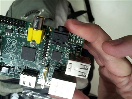
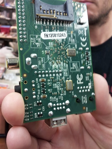
jbeale wrote:I just received my 2nd R-Pi, this one from stock (yay MCM Electronics) which took just a week to ship from Ohio to California. I was pleased, but surprised to see that the USB fuses F1, F2 are now just 0-ohm jumpers (photo below). I was able to confirm they measure less than 0.1 ohms. Is this the new standard going forward?
You've obviously recieved a Chinese pirate copy - it won't have all the features a proper Pi would have, such as not working with some keyboards, and the like.
Yes. After seeing how many people have decided to modify their boards with zero-ohm links, and having done some safety and reliability testing, we've decided that the best course of action is to remove the USB fuses from the design. Right now they're linked out, but on a subsequent board revision the pads will be removed entirely.
From Me Peg: Unlike on this Forum, I do not read every little thing on the org forum. . . BUT . . . is it just me or does this seem kind of sneaky? Or to put it another way. . . what happened to the "Open" in the open software/hardware world? Or did I miss the instructions on what to do with the two pi's I now own to make them more stable? No suggestions on buying the beagleboard Morgaine!
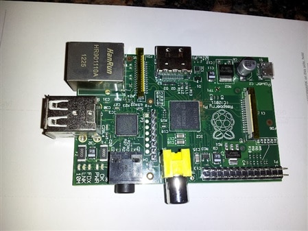
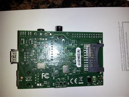
Thanks for the heads up on the 0-ohm change. Someone at my hackerspace Pi meetup last night told me he got his Pi from MCM last week, so I asked I could see it... and it was indeed "ohmless":
I'm very interested to see at a future meeting what will happen when we swap his Pi into someone's setup who is having trouble with USB devices that might be power related. With the USB host port polyfuses gone, I'm wondering if it is still be necessary to recommend using a self-powered hub for a WiFi adapter. (the GWU625 I've been using lists "Transmit : < 380mA. ; Receive: < 250mA").
English traditions aren't my strongest point I am afraid.
I could ask the free time question on the Pi forum, but I don't think that will make me more popular around there. (My credits are rather low already.)
For the polyfuse on the micro usb power input, I see on the eLinux wiki it is 1.1A with a hold current of 700mA. Does that mean the Pi can only draw 700mA before the polyfuse starts to gain resistance and decrease the 5V input?
Here's my understanding from a Littlefuse 2016L datasheet: a polyfuse has a trip current (in this case 1.1A) and a hold current (700mA). If you don't exceed the hold current, the polyfuse will not trip. If you exceed the trip current, the polyfuse will trip in some max number of seconds, dending on current and temperature. What happens between 700 mA and 1.1 A is not specified, and the currents vary with temperature. Polyfuses work by temperature-related changes to crystal structure, and as such work slowly and depend on temperature. Real fuses are better, but still trip pretty slowly.
So when you plug in that USB hard drive, if it draws 1.5A you'll trip in a couple of seconds. If you draw only 1 A, it will probably trip but may take a couple of minutes and meanwhile the polyfuse slowly gets more resistive and 5V drops to 4V, 3V, 2V, ... which may make your USB drive and your RasPi sad.
Fuses in general are crude devices designed to be the weak link in an electrical system. Home fuses are there to keep you from dying... from a fire caused by overheated wiring. They don't protect you from being electrocuted since the current needed to kill you is much smaller than a typical fuse. That's why you need a ground fault circuit interrupter (GFCI).
Similarly, the fuse in an electronic circuit keeps the circuit from drawing enough current to catch on fire. It takes a while for the fuse to get hot enough to blow -- plenty of time for permanent circuit damage. You need to have protection diodes large enough so that they don't overheat while the fuse trips. If you need accuracy and fast protection, you need a hot-swap controller.
Indeed. Supplying current protection for *whatever your customer may decide to connect together* is always going to be a fudge, unless the budget is large. Hopefully your customer will use a power supply with a sensible current rating that performs "current foldback" on being presented with a short circuit - the common 7805 regulator does this. If it sees a short on it's output then it will limit it's output current to (IIRC) 250mA, instead of the 1A+ that it is capable of supplying to a sensible load.
However, assume nothing! I saw a post on the Pi forum from a member that was considering using the +5 volt rail from a PC supply. Those things are rated at hundreds of Watts because they will deliver hundreds of Watts (with the +5V rail being the stiffest), so some form of input protection on your device is advisable. It might not save the device, but at least it may prevent a fire...
Before the things became ubiquitous (and reliable), early switched mode power supplies were renowned for sacrificing their transistors to save their output fuses.
I suppose that the polyfuse fix is a "pragmatic engineering solution" -
It is not a solution, just a fix, sort of a patch inspired by the community wisdom and trial and error approach of shorting the damn things to have a mouse or keyboard work.
A solution would be if at some moment they are really pragmatic and realize that while cutting cost is important, delivering a product that is expected to work at least with minimal standards.
BTW, still waiting to see "the list."
-J
"Pragmatic engineering solution" = fix / bodge / fudge / get you home, etc.
I'm not being an apologist, but over the last few weeks I've seen the company line delivered by The Names In Green And Red change from "there are no planned revisions" to "in a future revision x,y,z may happen..." Progress?
Board revisions are tricky - modern computers are RF engineering. There's only so many simulations you can run before actually having to cut some metal and test in the real world (I think they may have learned their lesson re. testing in the lab under "perfect" conditions the first time round, as have Seneca). If there's a board change planned, then the "pragmatic" thing to do would be to "workaround" minor issues 'til major revision time. Incremental software updates may be a bit of a ballache, but incremental hardware upates can be.... ugh! The turnaround time on any resulting issues is much longer than with software, will take longer to fix, and those users with buggy hardware are stuck with it.
It's not perfect, but then it's an imperfect world, especially in the realm of cheap consumer electronics. You can get away with publicly beta-ing firmware on an unsuspecting userbase occasionally, but doing the same with hardware is asking for trouble. Change is a holistic thing - changing one component can affect the whole assembly - and in ways that are not always predictable. Baby steps or giant leap?
That's quite accurate. Fast digital electronics is strongly concerned with transmission line propagation, impedance matching, crosstalk avoidance and ground planes, and that's even before you start worrying about EMC issues. Fortunately ARM hardware is clocked somewhat on the slow side, but even that isn't plain sailing.
Personally I started to worry when PCB best practice began to advise that track corners should be rounded. It's enough to make you head for the drinks cabinet ...
> Fortunately ARM hardware is clocked somewhat on the slow side
Are we talking about the 700MHz clock rate, or the clock rate for signals on the PCB?
I assume there is a clock divider in the SoC, so the PCB signals would run at
substantially lower frequency.
> Fast digital electronics is strongly concerned with transmission line propagation
I have heard that transmission line effects only matter if your conductor is longer than
about 15 cm for every 100 MHz in frequency, and there probably aren't any traces
longer than that on the RPi.
> track corners should be rounded
doesn't this make for huge gerbers? Are there any rounded corners on the RPi?
According to the schematics, the BCM2835 has a 19.2 MHz crystal, so it's multiplied for the internal 700 MHz +/- over/undeclock. The LAN9512 has a 25 MHz crystal, so it's multiplied to get 480 Mb/s.
Clock frequency is only part of the story. You also have to be concerned with signal edges: if a signal transitions faster than the round-trip delay on the wire it's driving you'll see reflections if the signal is not terminated properly. You can have a 300 Baud signal, but if the edges are too fast you'll get reflections. In the good old days of LSTTL, signal transitions were nice and slow so you only had to be concerned with reflections if the lines were really long. [Also, you didn't have to worry about ground bounce like you do nowadays -- different topic.]
From a brief scan of the PCB layouts (http://elinux.org/Rpi_Hardware#Schematic_.2F_Layout), I don't see any sharp right-angle turns. They're all rounded. OTOH, there are 45 degree bends that aren't rounded, but that's generally fine. I believe the most serious problem with right-angle turns is metal migration rather than reflections. With a sharp turn, the electron flow on a thin line concentrates at the inner corner and over time can damage the crystal structure of the metal. This has long been a factor in IC design, especially distributing power. A 45 degree bend or a curve spreads out the flow.
While RasPi doesn't have fast clocks on the board, it does have very fast differential pairs for HDMI, USB, and the DSI/CSI connectors. It's extremely important that the differential pairs are routed in a balanced way because any mismatch results in erroneous signals at the far end. They use interesting wiggles to compensate for BGA positions. It's OK for the lines of a differential pair to have small stubs as long as they're balanced.