That's quite accurate. Fast digital electronics is strongly concerned with transmission line propagation, impedance matching, crosstalk avoidance and ground planes, and that's even before you start worrying about EMC issues. Fortunately ARM hardware is clocked somewhat on the slow side, but even that isn't plain sailing.
Personally I started to worry when PCB best practice began to advise that track corners should be rounded. It's enough to make you head for the drinks cabinet ...
> Fortunately ARM hardware is clocked somewhat on the slow side
Are we talking about the 700MHz clock rate, or the clock rate for signals on the PCB?
I assume there is a clock divider in the SoC, so the PCB signals would run at
substantially lower frequency.
> Fast digital electronics is strongly concerned with transmission line propagation
I have heard that transmission line effects only matter if your conductor is longer than
about 15 cm for every 100 MHz in frequency, and there probably aren't any traces
longer than that on the RPi.
> track corners should be rounded
doesn't this make for huge gerbers? Are there any rounded corners on the RPi?
According to the schematics, the BCM2835 has a 19.2 MHz crystal, so it's multiplied for the internal 700 MHz +/- over/undeclock. The LAN9512 has a 25 MHz crystal, so it's multiplied to get 480 Mb/s.
Clock frequency is only part of the story. You also have to be concerned with signal edges: if a signal transitions faster than the round-trip delay on the wire it's driving you'll see reflections if the signal is not terminated properly. You can have a 300 Baud signal, but if the edges are too fast you'll get reflections. In the good old days of LSTTL, signal transitions were nice and slow so you only had to be concerned with reflections if the lines were really long. [Also, you didn't have to worry about ground bounce like you do nowadays -- different topic.]
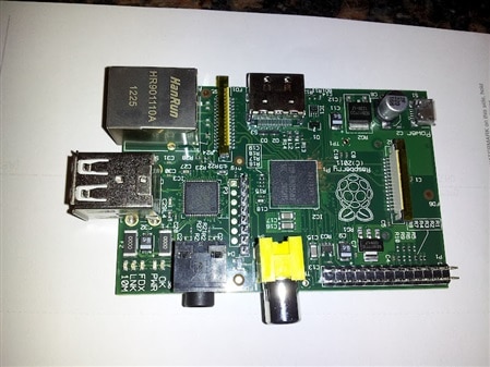
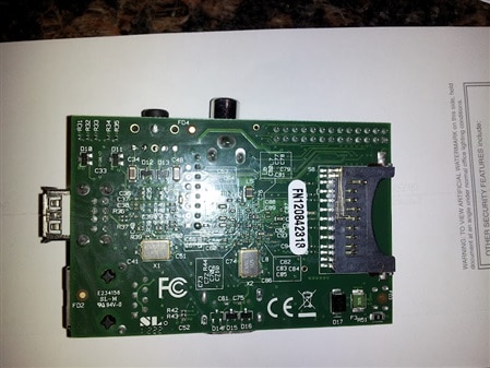
From a brief scan of the PCB layouts (http://elinux.org/Rpi_Hardware#Schematic_.2F_Layout), I don't see any sharp right-angle turns. They're all rounded. OTOH, there are 45 degree bends that aren't rounded, but that's generally fine. I believe the most serious problem with right-angle turns is metal migration rather than reflections. With a sharp turn, the electron flow on a thin line concentrates at the inner corner and over time can damage the crystal structure of the metal. This has long been a factor in IC design, especially distributing power. A 45 degree bend or a curve spreads out the flow.
While RasPi doesn't have fast clocks on the board, it does have very fast differential pairs for HDMI, USB, and the DSI/CSI connectors. It's extremely important that the differential pairs are routed in a balanced way because any mismatch results in erroneous signals at the far end. They use interesting wiggles to compensate for BGA positions. It's OK for the lines of a differential pair to have small stubs as long as they're balanced.