


Just a quick repost from something I posted on the Foundation forum as I reckon there's more technical knowledge over here!
I need some help with adapting some wiring.
I bought an item off eBay http://www.ebay.co.uk/itm/110940093247.
Now, I probably should have known better when I saw the HDMI label on it... I'm hoping that it is still decent definition, but I have a bit of a cable problem.
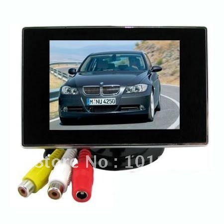
Here's a picture of the whole package:

Here's a couple of close-ups of the cable that attaches to the cable that comes out of the bottom of the screen. It's got 6 pins and looks a bit like a PS/2 cable. I _think_ it's a 6-pin DIN, but I could be talking out of my bum.


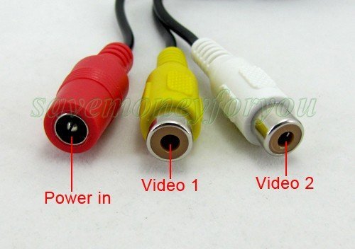
and one of the cable pack that comes with it.

I know, I know... Doesn't look promising.
So, there's a ground wire (black) and a 12V wire. Now, obviously it's a car rear view screen, so it's expected that the 12V wire is supposed to be connected to the rear tail light and then another wire goes back to power the tail light.
What I really want it to run it off the mains.
I have another screen that is _very_ similar, but has an adapter on the end for a 12V mains power supply (which I've got). Here's the display:

Another similar one:
And a close-up of the cable ends that I want to have for the new screen:
And this shows what the whole cable looks like on mine - note the little gadget that is on the live wire (which has a fuse inside it):
What I've done so far is to take the connector off the end of the 3.5" cable (the end that goes into the screen box) to reveal a red (live) wire, a ground and a yellow and a white (which must be the two composite inputs).
Now, what I think I have to do is to cut open the new input cable (with the 6 pin male connector), separate the wires and solder them to their equivalents on the 3.5" cable.
Does this sound right? I'd rather not a) blow the mains b) blow my head off c) blow the screen up d) blow the Pi up.
Hope someone can help.
--
Mike


