Hi,
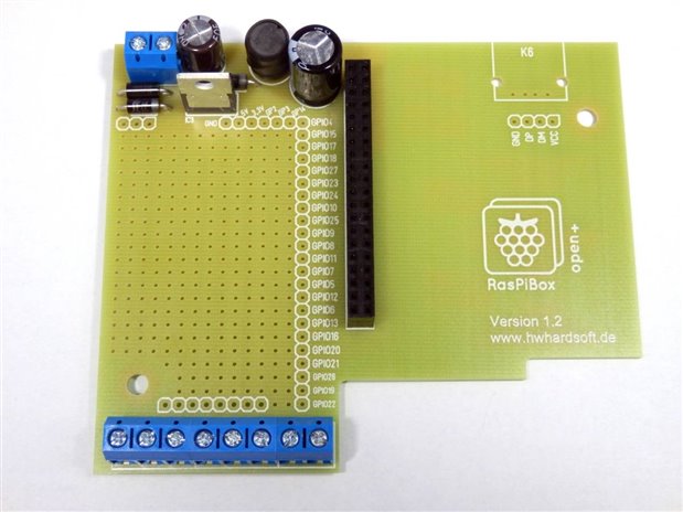
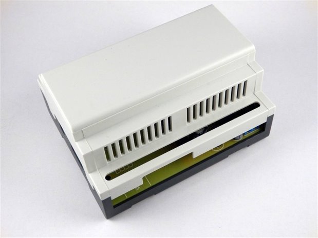
here some pictures of a new project from me. It's a prototyping plate with fitting DIN rail enclosure for the Raspberry Pi. Check this Link for more information
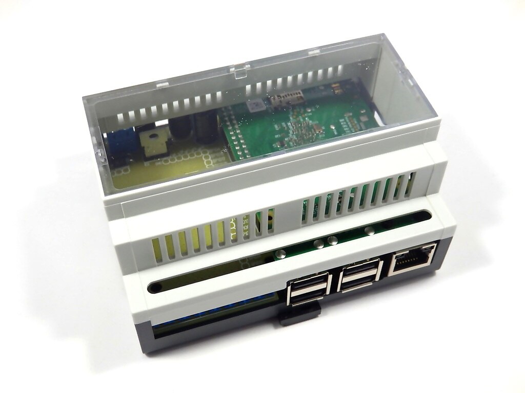
Message was edited by: Hartmut Wendt -new video and pictures of current version...
Hi,
here some pictures of a new project from me. It's a prototyping plate with fitting DIN rail enclosure for the Raspberry Pi. Check this Link for more information
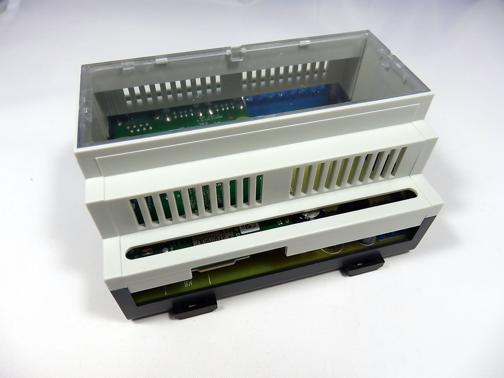
Message was edited by: Hartmut Wendt -new video and pictures of current version...

here is a short update about the RasPiBox enclosure. Since some days we are offering a reworked version 1.2 with some modifications for the Pi3 and PiZero>:
- stronger 5V DC voltage regulator with 1.7A output current
- full THT design, makes soldering easier for beginners
- wider sd card slot for the PiZero
- optional USB-A socket for the Pi Zero
Hi Hartmut,
Is that the actual supply circuit in the photographs? I'm guessing it is a switching regulator of course.
Do you have a schematic for this full THT design?
pls check this document for the circuit diagram:
Nice guide, it looks very easy to assemble.
It sounds a really great project. I like very much the solution. There is only a detail that sounds a bit strange to me. In the video you show a Raspberry PI A, that was slower than all the next models. Thinking to put a PI3, that is incredibly faster, are you sure that the reverse position mounting with the cooling holes make air circulating internally to the bottom of the PI board are reliable in a long or continuous usage? The processor in this enclosure result as the most closed part and the cooling ventilation does not include a fan, according with your images. Do you think it maybe the worth?
Enrico
Just a last not. I took a look to the (very well) documented circuit and assembly instructions. We should take in account that also the voltage regulator needs a sufficient dissipation surface and/or a forced ventilation. My worry is just that this very nice block will become too hot in few time.
Enrico
Dear Enrico,
we sold hundreds of this enclosure sets for the PI2 before and I never heard about such problems by our customers. Between the pcb and the Pi CPU is enough space for an air flow - and if you want a heat sink also. Please note: Usually the enclosure is mounted vertically in a control cabinet!
About the voltage regulator: Same as above. It's a very good tested design in several kits - for example in our mini arcade kits. For 24V input voltage and 2A output voltage it works without any heat sink. It's possible to mount a heat sink, because the regulator is placed to a position in the enclosure with enough height for vertical heat sink...
Yes the video is very old - from the beginning of this project over 2 years ago (as this thread ;-). We've started with a version for the first PI and changed the design over the years according the requirements of the actiual Pi version.
Best Regards
Hartmut