element14 Community
element14 Community
    Register Log In
  • Site
  • Search
  • Log In Register
  • Community Hub
    Community Hub
    • What's New on element14
    • Feedback and Support
    • Benefits of Membership
    • Personal Blogs
    • Members Area
    • Achievement Levels
  • Learn
    Learn
    • Ask an Expert
    • eBooks
    • element14 presents
    • Learning Center
    • Tech Spotlight
    • STEM Academy
    • Webinars, Training and Events
    • Learning Groups
  • Technologies
    Technologies
    • 3D Printing
    • FPGA
    • Industrial Automation
    • Internet of Things
    • Power & Energy
    • Sensors
    • Technology Groups
  • Challenges & Projects
    Challenges & Projects
    • Design Challenges
    • element14 presents Projects
    • Project14
    • Arduino Projects
    • Raspberry Pi Projects
    • Project Groups
  • Products
    Products
    • Arduino
    • Avnet Boards Community
    • Dev Tools
    • Manufacturers
    • Multicomp Pro
    • Product Groups
    • Raspberry Pi
    • RoadTests & Reviews
  • About Us
  • Store
    Store
    • Visit Your Store
    • Choose another store...
      • Europe
      •  Austria (German)
      •  Belgium (Dutch, French)
      •  Bulgaria (Bulgarian)
      •  Czech Republic (Czech)
      •  Denmark (Danish)
      •  Estonia (Estonian)
      •  Finland (Finnish)
      •  France (French)
      •  Germany (German)
      •  Hungary (Hungarian)
      •  Ireland
      •  Israel
      •  Italy (Italian)
      •  Latvia (Latvian)
      •  
      •  Lithuania (Lithuanian)
      •  Netherlands (Dutch)
      •  Norway (Norwegian)
      •  Poland (Polish)
      •  Portugal (Portuguese)
      •  Romania (Romanian)
      •  Russia (Russian)
      •  Slovakia (Slovak)
      •  Slovenia (Slovenian)
      •  Spain (Spanish)
      •  Sweden (Swedish)
      •  Switzerland(German, French)
      •  Turkey (Turkish)
      •  United Kingdom
      • Asia Pacific
      •  Australia
      •  China
      •  Hong Kong
      •  India
      •  Korea (Korean)
      •  Malaysia
      •  New Zealand
      •  Philippines
      •  Singapore
      •  Taiwan
      •  Thailand (Thai)
      • Americas
      •  Brazil (Portuguese)
      •  Canada
      •  Mexico (Spanish)
      •  United States
      Can't find the country/region you're looking for? Visit our export site or find a local distributor.
  • Translate
  • Profile
  • Settings
Raspberry Pi
  • Products
  • More
Raspberry Pi
Raspberry Pi Forum Is my raspberry unrepairable?
  • Blog
  • Forum
  • Documents
  • Quiz
  • Events
  • Polls
  • Files
  • Members
  • Mentions
  • Sub-Groups
  • Tags
  • More
  • Cancel
  • New
Join Raspberry Pi to participate - click to join for free!
Featured Articles
Announcing Pi
Technical Specifications
Raspberry Pi FAQs
Win a Pi
Raspberry Pi Wishlist
Actions
  • Share
  • More
  • Cancel
Forum Thread Details
  • State Suggested Answer
  • Replies 64 replies
  • Answers 2 answers
  • Subscribers 674 subscribers
  • Views 8559 views
  • Users 0 members are here
  • raspberry_pi
Related

Is my raspberry unrepairable?

Former Member
Former Member over 9 years ago

First of all I'm a beginner, so please don't judge me I know I did something bad.


SO, yesterday I was trying to make my raspberry pi 2 B to work with an external battery. I took a lithium polymer battery with 3.7v and 2500mah and I connect it to a booster. At first I was trying to hook it up to the micro usb input on the board and it didn't work. Then I look in youtube and I saw people plugging external batteries into the gpio pins. I joined the positive cable into the the first 5v pin and the negative cord into the first 3.3v pin and vs. Although when I connected the positive cable into the first 5v pin and the negative into the 3.3v pin for the second time with longer time touching them, it sparked and then I saw it left a kind of cut in both gpio pins. Now this morning that I try to power up my raspberry with a normal micro usb cable, I can feel the board getting warm(normal warm) but the led does not turn on.


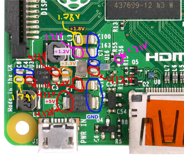
In the pictures attached, the voltmeter says 4.12 v output but yesterday I adjust it to 5.2v also using the voltmeter but I don't know why it shows 4.12v now... And also in the mark on gpio is the same in the other side (the first 3.3v pin).


Is there anything I can do? Or is it burnout forever?


Thanks in advance.

Attachments:
image
image
image
image
  • Sign in to reply
  • Cancel
Parents
  • gregoryfenton
    0 gregoryfenton over 9 years ago

    May I interject and offer an opinion here?

    Consider the time taken to monitor this thread, probe the board and buy all the parts necessary to follow advice offered here.

    How long before your costs (including an hourly rate) outweigh the value of what amounts to a throwaway computer?

    One of the aims of the Raspberry Pi project was to put computers in the hands of children and were designed to be cheap to replace when careless hands did something that resulted in a dead board.


    Greg

    • Cancel
    • Vote Up 0 Vote Down
    • Sign in to reply
    • Verify Answer
    • Cancel
  • rew
    0 rew over 9 years ago in reply to gregoryfenton

    Greg, the time vs real dollars tradeoff can be very different for other people.


    On the other hand, there is a learning experience which will be useful at a  later date but the value currently is unknown.


    Mauricio: The LM1117-1.8 is a reaonsable LDO to make 1.8V from the 5V. Similarly the LM1117-3.3 is a good one for the 3.3V rail. In fact rpi-1 used one for the 3.3V rail. [update: And for the 1.8V rail as well!). Take care that you put the recommended capacitors near the LM1117. Check the datasheet for the VENDOR that you're using. TI might have other recommendations than ST for example.


    Finding a place to inject 3.3V is easy: The GPIO will do fine.


    Finding a place to inject 1.8V is more difficult. Hmm... Can you find C108, R57 and R58? Either side of R57 or C108 will do, but R58 being "not fitted" may be easier to solder to. (the other side of R58 is GND. Can you find C8 near there? One side is GND the other is 1.8V. Might be a lot bigger than the other ones.

    • Cancel
    • Vote Up +1 Vote Down
    • Sign in to reply
    • Verify Answer
    • Cancel
  • bbolo1
    0 bbolo1 over 9 years ago in reply to rew

    I think for Mauricio, this is a good learning experience. Even if the board turns out in the end to be fried, at least he will remain with some valuable learned lessons.

    The bad thing about RPI2 is that the schematic is not available.

    I made some rough sketches over a high res photo of the RPI2 power supply area.

    U3 and the famous U16 (the flash camera shy chip) are switching regulators.

    U3 takes 5V (from the USB receptacle) and provides 3.3V and 1.8V power rails. The camera shy chip (U16) provides the 1.2V power rail.


    And now the debugging part. Before going any further, I want you to know you will need to desolder some parts to be 100% sure the bad parts are removed. Rather than throw away a defective board, it can still provide you some electrical debugging lessons.

    Since both U3 and U16 are buck regulator chips, you might be able to avoid desoldering them.

    Take a look at the attached picture and make some measurements while powering the board from an USB adapter.

    1. Check the voltage on the point where you should have 3.3V

    2. do the same for the point where you should have 1.8V and 1.2V


    Please come back and tell what voltages did you measured. Based on your findings, the next steps will probably involve desoldering a few parts from the board.

    image

    • Cancel
    • Vote Up +1 Vote Down
    • Sign in to reply
    • Verify Answer
    • Cancel
  • shabaz
    0 shabaz over 9 years ago in reply to bbolo1

    Wow - great detective work!

    Just to add to that, based on your photo, it looks like the U3 device is PAM2306A, because on a hunch I checked the Pi Compute Module schematic (which is published) and the pins on U3 appear to match that schematic. So it is probably a near-identical schematic for that portion (extract of the Pi CM schematic under fair use):

    image

    Interesting how the part in your photo is clearly not marked as that device though (the datasheet specifically indicates the package marking). However, it is highly likely to be the same part, or one in the same family.

    I think it is important for use to know this area of the circuit, because so many questions come up related to this topic in some way.

    Just goes to show how important schematics are for those who want to explore more.

    • Cancel
    • Vote Up +2 Vote Down
    • Sign in to reply
    • Verify Answer
    • Cancel
Reply
  • shabaz
    0 shabaz over 9 years ago in reply to bbolo1

    Wow - great detective work!

    Just to add to that, based on your photo, it looks like the U3 device is PAM2306A, because on a hunch I checked the Pi Compute Module schematic (which is published) and the pins on U3 appear to match that schematic. So it is probably a near-identical schematic for that portion (extract of the Pi CM schematic under fair use):

    image

    Interesting how the part in your photo is clearly not marked as that device though (the datasheet specifically indicates the package marking). However, it is highly likely to be the same part, or one in the same family.

    I think it is important for use to know this area of the circuit, because so many questions come up related to this topic in some way.

    Just goes to show how important schematics are for those who want to explore more.

    • Cancel
    • Vote Up +2 Vote Down
    • Sign in to reply
    • Verify Answer
    • Cancel
Children
  • bbolo1
    0 bbolo1 over 9 years ago in reply to shabaz

    Thank you! I think you did a great job too. image I wasn't able to find the mysterious U3, dual regulator chip.

    BTW, I used the RPI2 hi res photo available on wikipedia. I don't think I would be able to take a better picture image

    Now, having your input, I think we should have at least some good knowledge about RPI2's power supply.

    Since I was assuming the U3 is a dual buck regulator and if in Mauricio's case, the FETs are broken in this chip, he might get along with only desoldering the L1 and L2 inductors (assuming the U16 - camera shy chip is not broken). If U16 is broken as well, then desoldering L3 as well would at least isolate the CPU's power rails from the regulators.

    If the 3 power rails (3.3, 1.8 and 1.2V) are not drawing excessive amounts of current, then there is still hope.

    • Cancel
    • Vote Up +1 Vote Down
    • Sign in to reply
    • Verify Answer
    • Cancel
  • Former Member
    0 Former Member over 9 years ago in reply to bbolo1

    Hi!


    Sorry for late responding, I was doing a final exam. x.x Anyways mine is different when it comes to the voltages for the 5v.

    And by the way, when I plugged the raspberry pi to my computer it showed me a message saying the usb is taking a lot of power; I don't know if it's an important information.

    This are my measurements:

    image


    Thank you for taking your time to teach me image

    • Cancel
    • Vote Up +1 Vote Down
    • Sign in to reply
    • Verify Answer
    • Cancel
  • shabaz
    0 shabaz over 9 years ago in reply to Former Member

    Hi Maurico,


    Did you measure the orange location? That one is very

    Important to measure. There is a good chance it may be higher than the expected 3.3V : ( which would be bad news. Anyway, it needs checking.

    • Cancel
    • Vote Up 0 Vote Down
    • Sign in to reply
    • Verify Answer
    • Cancel
  • Former Member
    0 Former Member over 9 years ago in reply to shabaz

    Thank you for the reminder! It's at 0.40v.

    • Cancel
    • Vote Up 0 Vote Down
    • Sign in to reply
    • Verify Answer
    • Cancel
  • bbolo1
    0 bbolo1 over 9 years ago in reply to Former Member

    Hi Mauricio,

    This is an interesting finding.

    It seems both the 1.2 and 1.8V rails are quite ok in your case. However, the 3.3V rail being so low is not good. There are many chips on the board using the 3.3V power rail. If the CPU is getting really hot when powering the board, then it is probably gone. What about the ethernet and USB hub chip? This the one with the SMSC logo onto it. Is this chip getting hot too?

    Other ideas would include to desolder L1, which is the inductor used by the 3.3V regulator. By doing so, you will disconnect the 3.3V rail. If afterwards, the 5V rail is quite normal (the voltmeter readings should show a value close to 5V), then this means the fault is only in the 3.3V rail and it can be in one or more chips using it.

    To definitely know which chips are faulty, you can power the board from USB (having the L1 inductor disconnected, thus the board's 3.3V switching regulator won't interfere) and then connect an external 3.3V power supply (you can connect it at the point where you should have 3.3V) capable of delivering a few amps (at least). Then, all the faulty chips should get very hot.

    • Cancel
    • Vote Up 0 Vote Down
    • Sign in to reply
    • Verify Answer
    • Cancel
  • rew
    0 rew over 9 years ago in reply to bbolo1

    With the 3.3V at 0.4V the SMSC chip (the lan chip) will not be powered. It is powered only from the 3.3V rail. So with the power rail at 0.4V, it doesn't have the power to become hot.


    The 3.3V is used by:

    * the lan chip. (main power).

    * the SD card (main power)

    * the CPU (as IO voltage).


    If you have a lab power supply, setting the voltage to 3.3V and the current to say 40mA, remove the SD card  and power the 3.3V rails through the GPIO pins. If it goes into current limit that might be the LAN chip which might not even be broken. Increase the current to about 100mA. It should stay below that. All this of course afteryou've disconnected the regulator from the 3.3V by removing L1. as bbolo1 suggests.

    • Cancel
    • Vote Up +1 Vote Down
    • Sign in to reply
    • Verify Answer
    • Cancel
  • Former Member
    0 Former Member over 9 years ago in reply to bbolo1

    Ok so, I tried to power it through my home plug and the 5v (red ones) are now at 4.85v, and all the others stayed the same voltages. All chips gets hot( they feel pretty much the same temperature). I didn't tried to desolder anything since the new voltage for the 5v changed. Should I still desolder anything or plans changed?


    @Roger Wolff I don't have a lab power supply, for now I can use a battery right? I can perhaps buy a low mA battery. Are lab power supply really usefull?

    • Cancel
    • Vote Up 0 Vote Down
    • Sign in to reply
    • Verify Answer
    • Cancel
  • rew
    0 rew over 9 years ago in reply to Former Member

    Yes, lab power supplies are really useful!


    (note that you mentioned the word "really" and I answered with the word "really" in my response. Those are different meanings of a word spelled and written the same. Think about it. :-) )


    A lab powersupply has a configurable current limit. This means that you can set that limit at say 30% above what you expect your circuit to use, and then not blow stuff up if there is a mistake in a circuit.


    Example: I'm working on a motor-control-PCB. During startup, the CPU apparently tells the powerstage: connect V+ to motor pin A, while at the same time: connect GND to motor pin A. Of course that should never happen, but apparently it happens during startup. So far the "current limit" led of the powersupply blinks an instant and nothing blows up. If I connect a good LIPO battery as the powersupply I'm pretty sure that the FET switches would blow up.


    If you say that your chips get hot, that means that something is seriously wrong. A hint that nothing more can be done.

    If you still measure 0.4V on the 3.3V line, then it is very difficult for the LAN chip to become hot: It doesn't have any power. I question the observation....


    If the 3.3V line is "shorted" to GND (about 0.4V) by the regulator, then I can imagine the CPU getting hot. It MIGHT have a diode from its 1.2V supply to the 3.3V IO voltage. Normally not conductive, but now suddenly a current can flow.


    Many people confuse mAh ratings and mA ratings of batteries. I have a 3Ah LIPO battery rated at 120A. It can deliver 3A for an hour, or say 0.3A for 10 hours. But it can also deliver 120A for about 1/40th of an hour (90 seconds). Take a 10x smaller version of that battery and it says "300mAh", and you'd think: find that won't harm my 'pi. But it can deliver 12A, quite a lot end easily enough to damage a 'pi.

    • Cancel
    • Vote Up +1 Vote Down
    • Sign in to reply
    • Verify Answer
    • Cancel
  • johnbeetem
    0 johnbeetem over 9 years ago in reply to rew

    Roger Wolff wrote:


    A lab powersupply has a configurable current limit. This means that you can set that limit at say 30% above what you expect your circuit to use, and then not blow stuff up if there is a mistake in a circuit.

    Yes, that is an extremely useful feature.  Another fun thing you can do with a lab supply is to clear a thin conductive bridge that's shorting together two signals because of a PC board defect.  You set your lab supply voltage to 0.5V or so and set the current way up to 10A or so.  Then you connect the leads to the two signals.  If the bridge is thin enough, the 10A will blow the bridge like a fuse and the 0.5V makes sure you don't apply too much voltage when the short clears.  This only works for some shorts, but when it works it rescues a board.

    • Cancel
    • Vote Up 0 Vote Down
    • Sign in to reply
    • Verify Answer
    • Cancel
  • rew
    0 rew over 9 years ago in reply to johnbeetem

    Absolutely. Did exactly that a week or two ago. Although my lab powersupply does not go any further than 3A, but it worked. :-)

    • Cancel
    • Vote Up +1 Vote Down
    • Sign in to reply
    • Verify Answer
    • Cancel
element14 Community

element14 is the first online community specifically for engineers. Connect with your peers and get expert answers to your questions.

  • Members
  • Learn
  • Technologies
  • Challenges & Projects
  • Products
  • Store
  • About Us
  • Feedback & Support
  • FAQs
  • Terms of Use
  • Privacy Policy
  • Legal and Copyright Notices
  • Sitemap
  • Cookies

An Avnet Company © 2025 Premier Farnell Limited. All Rights Reserved.

Premier Farnell Ltd, registered in England and Wales (no 00876412), registered office: Farnell House, Forge Lane, Leeds LS12 2NE.

ICP 备案号 10220084.

Follow element14

  • X
  • Facebook
  • linkedin
  • YouTube