element14 Community
element14 Community
    Register Log In
  • Site
  • Search
  • Log In Register
  • Community Hub
    Community Hub
    • What's New on element14
    • Feedback and Support
    • Benefits of Membership
    • Personal Blogs
    • Members Area
    • Achievement Levels
  • Learn
    Learn
    • Ask an Expert
    • eBooks
    • element14 presents
    • Learning Center
    • Tech Spotlight
    • STEM Academy
    • Webinars, Training and Events
    • Learning Groups
  • Technologies
    Technologies
    • 3D Printing
    • FPGA
    • Industrial Automation
    • Internet of Things
    • Power & Energy
    • Sensors
    • Technology Groups
  • Challenges & Projects
    Challenges & Projects
    • Design Challenges
    • element14 presents Projects
    • Project14
    • Arduino Projects
    • Raspberry Pi Projects
    • Project Groups
  • Products
    Products
    • Arduino
    • Avnet & Tria Boards Community
    • Dev Tools
    • Manufacturers
    • Multicomp Pro
    • Product Groups
    • Raspberry Pi
    • RoadTests & Reviews
  • About Us
    About the element14 Community
  • Store
    Store
    • Visit Your Store
    • Choose another store...
      • Europe
      •  Austria (German)
      •  Belgium (Dutch, French)
      •  Bulgaria (Bulgarian)
      •  Czech Republic (Czech)
      •  Denmark (Danish)
      •  Estonia (Estonian)
      •  Finland (Finnish)
      •  France (French)
      •  Germany (German)
      •  Hungary (Hungarian)
      •  Ireland
      •  Israel
      •  Italy (Italian)
      •  Latvia (Latvian)
      •  
      •  Lithuania (Lithuanian)
      •  Netherlands (Dutch)
      •  Norway (Norwegian)
      •  Poland (Polish)
      •  Portugal (Portuguese)
      •  Romania (Romanian)
      •  Russia (Russian)
      •  Slovakia (Slovak)
      •  Slovenia (Slovenian)
      •  Spain (Spanish)
      •  Sweden (Swedish)
      •  Switzerland(German, French)
      •  Turkey (Turkish)
      •  United Kingdom
      • Asia Pacific
      •  Australia
      •  China
      •  Hong Kong
      •  India
      •  Japan
      •  Korea (Korean)
      •  Malaysia
      •  New Zealand
      •  Philippines
      •  Singapore
      •  Taiwan
      •  Thailand (Thai)
      •  Vietnam
      • Americas
      •  Brazil (Portuguese)
      •  Canada
      •  Mexico (Spanish)
      •  United States
      Can't find the country/region you're looking for? Visit our export site or find a local distributor.
  • Translate
  • Profile
  • Settings
Raspberry Pi
  • Products
  • More
Raspberry Pi
Raspberry Pi Forum Building a Pi WiFi radio receiver controlled by vintage aircraft instruments. Some pointers, please ?
  • Blog
  • Forum
  • Documents
  • Quiz
  • Events
  • Polls
  • Files
  • Members
  • Mentions
  • Sub-Groups
  • Tags
  • More
  • Cancel
  • New
Join Raspberry Pi to participate - click to join for free!
Featured Articles
Announcing Pi
Technical Specifications
Raspberry Pi FAQs
Win a Pi
Raspberry Pi Wishlist
Actions
  • Share
  • More
  • Cancel
Forum Thread Details
  • State Suggested Answer
  • Replies 30 replies
  • Answers 16 answers
  • Subscribers 706 subscribers
  • Views 6291 views
  • Users 0 members are here
  • raspberry_pi
Related

Building a Pi WiFi radio receiver controlled by vintage aircraft instruments. Some pointers, please ?

marco'polo
marco'polo over 6 years ago

Hello, new to this forum, I am seeking some help to get started in the right direction with this project.


My goal is to build a WiFi radio receiver with speakers operated by RP and controlled by vintage aircraft cockpit instruments, probably a Pi3+ (?). It needs to look nice and be original.


Here's an example of the radio part, with credits to Bob Rathbone

https://bobrathbone.com/raspberrypi/pi_internet_radio.html

There are exquisite instructions and manuals by him on how to build the radio part of this project so that is not my question.

image


Here's the twist and where I need to help getting started. I have 5 of these 80s analog, precise, unused instrument controllers. I would like to incorporate these to replace the stock rotary dials and control channel and volume. It would look cool, be original, but.... I don't know how to use the controller to feed inputs to the RP.


imageimageimage

Idea1: In the back there is a 37 pinout D-bus terminal. The most elegant would be to buy some female 37 pin board converter and find a way to feed the input to the RP, perhaps via the GPIO of the RP. I don't have a mapping of each pin's purpose, the closest I could find is in the pic below.

Does anyone have an idea how to discover the use of each pin and how to turn that into a listening variable input into a program on the RP ?

image


Idea2: If all else fails, there may be a brute force method of removing the backplate and gluing some rotary knob controller directly onto the disc. Might function but not elegant.


Expanding the project, I could even add some electric dial powered instruments/gauges to show volume level setting by feeding the right input back to the instrument.


imageimage


I would greatly appreciate if anyone could give me some general steps and ideas to follow especially for idea 1 above. THANKS!

  • Sign in to reply
  • Cancel
Parents
  • jc2048
    0 jc2048 over 6 years ago

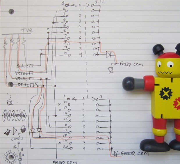
    In case you're not clear about the schematic, the frequency switches encode negative-logic BCD [Binary Coded Decimal].


    One slight disadvantage with the scheme that the original designer used is that, on the setting for '7', there are two diodes in series on a couple of the outputs, so the drop across them is going to be a fair bit more than where there is just one diode, and the corresponding low-level will then be higher. You might want to measure that voltage level with a meter and then take a view as to whether you were happy with it for whatever logic it was going to be connected to.

    • Cancel
    • Vote Up 0 Vote Down
    • Sign in to reply
    • Verify Answer
    • Reject Answer
    • Cancel
Reply
  • jc2048
    0 jc2048 over 6 years ago

    In case you're not clear about the schematic, the frequency switches encode negative-logic BCD [Binary Coded Decimal].


    One slight disadvantage with the scheme that the original designer used is that, on the setting for '7', there are two diodes in series on a couple of the outputs, so the drop across them is going to be a fair bit more than where there is just one diode, and the corresponding low-level will then be higher. You might want to measure that voltage level with a meter and then take a view as to whether you were happy with it for whatever logic it was going to be connected to.

    • Cancel
    • Vote Up 0 Vote Down
    • Sign in to reply
    • Verify Answer
    • Reject Answer
    • Cancel
Children
  • phoenixcomm
    0 phoenixcomm over 6 years ago in reply to jc2048

    jc2048 you are sort of on the right track. but even you could say BCD it is not. But they do add like BCD. like I said a 700K = 400K + 200k + 100k. but the diodes make it crazy. like i said to build a spreadsheet for the three switches, as they all will be a little different. Connect Negative to the common and start switching and probing.    BTW since you are not pulling up the output lines, they will float.  the easy way if you don't want to probe is to connect a breakout with your LEDs and a resistor in series. then to 4 or 5 volts, and the grounded ones will lite. fins!

    • Cancel
    • Vote Up +2 Vote Down
    • Sign in to reply
    • Verify Answer
    • Cancel
  • jc2048
    0 jc2048 over 6 years ago in reply to phoenixcomm

    Thanks phoenixcomm


    I know you and Micheal have basically answered the question. I was just emphasising to Marco that the switches do the encoding, so if he's careful with how he arranges his IO, he can have the numbers by simply inverting the code that comes in.


    Here's how it looks if you redraw the two switch poles so that it's a bit easier to understand [I find the original a bit confusing, even though it's a very nice piece of draughting work]. That's for the 10s of kHz switch, but the same applies to the other two.


    I've shown the current flows in red for the case where '7' is selected. The extra diodes are necessary for that case because there are only two switch poles, but three lines need to be pulled down.


    image


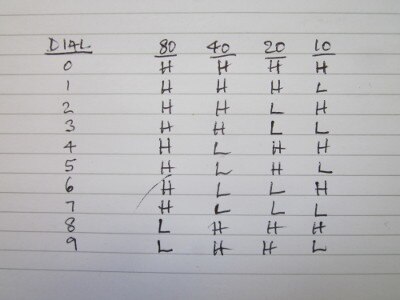
    The truth table you get if you work through all the switch positions is this


    image


    that's negative-logic BCD. Invert all the levels, so that it's positive-true, and you're back to binary.


    I think I would have suggested IO expanders on a plug-in board on the back of each head unit, with power and I2C running along to the Pi, but Michael's suggestion of a Pi shield makes more sense [I didn't realise such things were available, though it's a fairly obvious thing to make and sell].

    • Cancel
    • Vote Up +1 Vote Down
    • Sign in to reply
    • Verify Answer
    • Reject Answer
    • Cancel
  • michaelkellett
    0 michaelkellett over 6 years ago in reply to jc2048

    Hello John,

    You mentioned it earlier but your enhanced schematic (amazing app that PencilCAD ! image) really brings the point home - the diodes mean that the switches won't pull very low.

    For correct operation of the MCP23017 used in most I2C expanders you need to get below 0.2Vcc (0.66V on 3.3V systems, 1V on 5V systems).

    The two diodes in series mean that 20k and 10k will pulls down to about 1.2V (if silicon diodes).


    You could still use the MCP23017 but the 10k and 20k lines would need some additional components for it to work.


    Alternatively you could use a micro (an Arduino would do, a 3.3V one will interface mores easily with the RPi) and use its built in ADC to measure the 10k and 20k signals.


    MK

    • Cancel
    • Vote Up +2 Vote Down
    • Sign in to reply
    • Verify Answer
    • Reject Answer
    • Cancel
  • phoenixcomm
    0 phoenixcomm over 6 years ago in reply to jc2048

    jc2048 neat redraw in the original UAD. This is what you normally end up with. having BCD outputs help a lot. Most of the logic has one diode drop but some have two, so the expanders are out, unless each output was pulled up by its own resistor. From what I understand he wants multiple heads, that is why I suggested the mega, it handles all of the i/o on one board and they can talk fairly easily of CAN bus, or RS-485 but this you have to poll and I think it is a drag on a CPU, while CAN is not a polling system is bidirectional. Depending on how the Pi wants the frequency presented most likely in decimal or ASCI? ether way the BCD converted whatever and then added where the dial is a 7 you will end up with three values (int) High, medium and low.  ie decimalfreq = (high * 1000) + (medium * 100) + (low * 10 )  or  just put them in to an array freq and use itoa() function or toascii() singly.

    • Cancel
    • Vote Up +3 Vote Down
    • Sign in to reply
    • Verify Answer
    • Reject Answer
    • Cancel
  • marco'polo
    0 marco'polo over 6 years ago in reply to jc2048

    Thank you for all the tips and the sketch, I'm still trying to understand how to plug that.

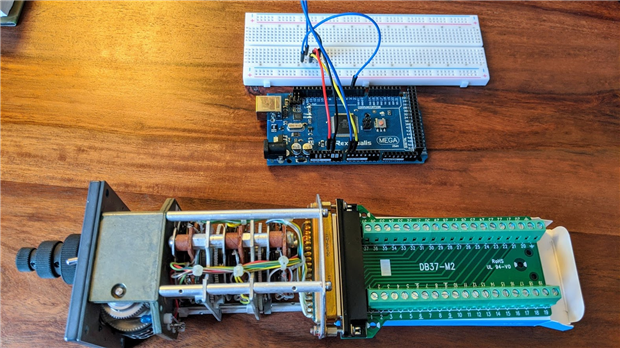
    Well I decided to go with phoenixcomm 's advice and also learn a little more, so I bought an Arduino MEGA kit, and followed enough tutorials to be dangerous. I have a little program that can read my 16 analog inputs on the MEGA Serial Monitor. Enough to start playing and read values. Once I have that down, I'll worry about porting them over the the Pi and the radio program.


    Now pls indulge me with another beginner's question : Now I need to map my pin# to the Arduino inputs. For the 10 Frequency selector pin I think I port each to an analog MEGA input. But how do I identify pin# for Ground and VCD ? I don't mind trial and error but I am afraid of frying something. Also for VCD should I start with the 3.3V or 5V feed from the MEGA ? I'm slightly out of my league here, perhaps my question is not even the right one.


    Thanks !

    Marc

    image

    • Cancel
    • Vote Up 0 Vote Down
    • Sign in to reply
    • Verify Answer
    • Cancel
  • phoenixcomm
    0 phoenixcomm over 6 years ago in reply to marco'polo

    marco  No use digital inputs!! BTW You said earlier that you where thinking about giving some heads away.. If you still a go. Im in. Thanks Cris

    • Cancel
    • Vote Up 0 Vote Down
    • Sign in to reply
    • Verify Answer
    • Cancel
  • marco'polo
    0 marco'polo over 6 years ago in reply to phoenixcomm

    Yes of course, only analog inputs on the MEGA, phoenixcomm


    I'd be glad to ship you one unit if you're in the USA/CAN and will hope that you can help me to better connect the power source this way. Can you direct-message me your address and I'll get one unit out ?


    Also FYI I think you are tagging the wrong marco in your replies. I am marco'polo


    Thanks.

    • Cancel
    • Vote Up 0 Vote Down
    • Sign in to reply
    • Verify Answer
    • Cancel
  • phoenixcomm
    0 phoenixcomm over 6 years ago in reply to marco'polo

    Nope, you must use the digital I/0 with pullups! not analog..  pins 22 - 52 are always digital

    • Cancel
    • Vote Up +3 Vote Down
    • Sign in to reply
    • Verify Answer
    • Cancel
  • marco'polo
    0 marco'polo over 6 years ago in reply to phoenixcomm

    Hello phoenixcomm , are you still interested in receiving one ADF head unit ? Let me know. I will need your shipping details. I modified my profile to allow being contacted but i am still not sure this platform allows DM.

    Either way let me know here and we'll find a way. Thanks

    • Cancel
    • Vote Up +1 Vote Down
    • Sign in to reply
    • Verify Answer
    • Cancel
element14 Community

element14 is the first online community specifically for engineers. Connect with your peers and get expert answers to your questions.

  • Members
  • Learn
  • Technologies
  • Challenges & Projects
  • Products
  • Store
  • About Us
  • Feedback & Support
  • FAQs
  • Terms of Use
  • Privacy Policy
  • Legal and Copyright Notices
  • Sitemap
  • Cookies

An Avnet Company © 2026 Premier Farnell Limited. All Rights Reserved.

Premier Farnell Ltd, registered in England and Wales (no 00876412), registered office: Farnell House, Forge Lane, Leeds LS12 2NE.

Follow element14

  • X
  • Facebook
  • linkedin
  • YouTube