element14 Community
element14 Community
    Register Log In
  • Site
  • Search
  • Log In Register
  • Community Hub
    Community Hub
    • What's New on element14
    • Feedback and Support
    • Benefits of Membership
    • Personal Blogs
    • Members Area
    • Achievement Levels
  • Learn
    Learn
    • Ask an Expert
    • eBooks
    • element14 presents
    • Learning Center
    • Tech Spotlight
    • STEM Academy
    • Webinars, Training and Events
    • Learning Groups
  • Technologies
    Technologies
    • 3D Printing
    • FPGA
    • Industrial Automation
    • Internet of Things
    • Power & Energy
    • Sensors
    • Technology Groups
  • Challenges & Projects
    Challenges & Projects
    • Design Challenges
    • element14 presents Projects
    • Project14
    • Arduino Projects
    • Raspberry Pi Projects
    • Project Groups
  • Products
    Products
    • Arduino
    • Avnet & Tria Boards Community
    • Dev Tools
    • Manufacturers
    • Multicomp Pro
    • Product Groups
    • Raspberry Pi
    • RoadTests & Reviews
  • About Us
  • Store
    Store
    • Visit Your Store
    • Choose another store...
      • Europe
      •  Austria (German)
      •  Belgium (Dutch, French)
      •  Bulgaria (Bulgarian)
      •  Czech Republic (Czech)
      •  Denmark (Danish)
      •  Estonia (Estonian)
      •  Finland (Finnish)
      •  France (French)
      •  Germany (German)
      •  Hungary (Hungarian)
      •  Ireland
      •  Israel
      •  Italy (Italian)
      •  Latvia (Latvian)
      •  
      •  Lithuania (Lithuanian)
      •  Netherlands (Dutch)
      •  Norway (Norwegian)
      •  Poland (Polish)
      •  Portugal (Portuguese)
      •  Romania (Romanian)
      •  Russia (Russian)
      •  Slovakia (Slovak)
      •  Slovenia (Slovenian)
      •  Spain (Spanish)
      •  Sweden (Swedish)
      •  Switzerland(German, French)
      •  Turkey (Turkish)
      •  United Kingdom
      • Asia Pacific
      •  Australia
      •  China
      •  Hong Kong
      •  India
      • Japan
      •  Korea (Korean)
      •  Malaysia
      •  New Zealand
      •  Philippines
      •  Singapore
      •  Taiwan
      •  Thailand (Thai)
      • Vietnam
      • Americas
      •  Brazil (Portuguese)
      •  Canada
      •  Mexico (Spanish)
      •  United States
      Can't find the country/region you're looking for? Visit our export site or find a local distributor.
  • Translate
  • Profile
  • Settings
Raspberry Pi
  • Products
  • More
Raspberry Pi
Raspberry Pi Forum Raspberry Pi {Help!}
  • Blog
  • Forum
  • Documents
  • Quiz
  • Events
  • Polls
  • Files
  • Members
  • Mentions
  • Sub-Groups
  • Tags
  • More
  • Cancel
  • New
Join Raspberry Pi to participate - click to join for free!
Featured Articles
Announcing Pi
Technical Specifications
Raspberry Pi FAQs
Win a Pi
Raspberry Pi Wishlist
Actions
  • Share
  • More
  • Cancel
Forum Thread Details
  • State Suggested Answer
  • Replies 6 replies
  • Answers 1 answer
  • Subscribers 675 subscribers
  • Views 790 views
  • Users 0 members are here
  • help
  • monitor
  • mods
  • raspberry_pi
  • raspberrypi
Related

Raspberry Pi {Help!}

Former Member
Former Member over 11 years ago

Hey,

I have a raspberry pi and I bought this little monitor for it: http://www.amazon.com/3-5-Inch-TFT-Monitor-Automobile/dp/B0045IIZKU/ref=sr_1_1?ie=UTF8&qid=1395790355&sr=8-1&keywords=Mini+Lcd+Screen+Raspberry+Pi

It has the same "type" RCA port as the pi, so I wanted to take the port of the pi and monitor so I didn't have to drag around extra stuff and I thought it would be easy and a learning experience.

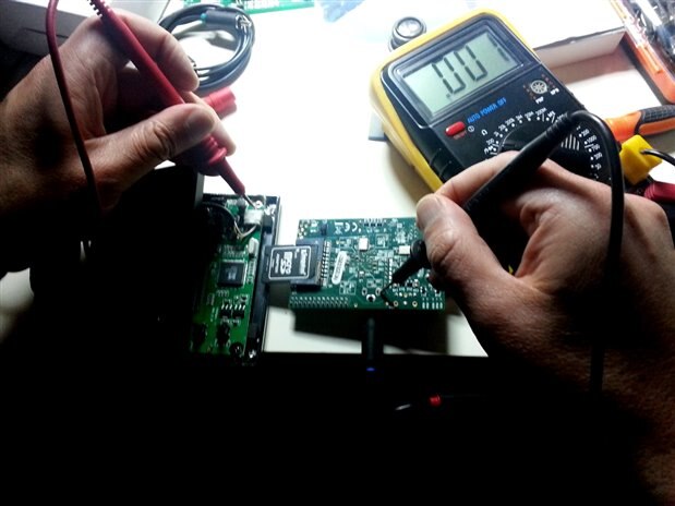
Unfortunately it is not working, the pi itself seems fine the area around the port may be damaged, but the rest if not all still works. As for the monitor, I have no idea if it is still working, it has to have a signal to work and the pi/monitor isn't responding to each other. I've attached some photos of what they currently "look like".

Red is Positive

Black is Ground

Yellow is Video

White is Sound

Red and black I have been connecting to the battery (to power the monitor).

Yellow I have been connecting to the pi.

And I have not been using the white.

Attachments:
image
image
image
image
image
  • Sign in to reply
  • Cancel
Parents
  • iagorubio
    0 iagorubio over 11 years ago

    Hello Michael.


    Sorry for the delay, had a couple of hard days at work.


    Whatching the pictures again I am not so sure about what I told you because those cables don't seem come be from the RCA connectors.


    The power line are those cables with the fuse on them. If you unscrew the fuse holder you can use alligator clips to power the screen.


    Just grab the positive to the wire coming out of the fuse holder and the negative to the power RCA connector with care of not touching the pin into it.


    Fullscreen 3438.contentimage_176392.html Download
    <html><head><title>Jive SBS</title></head>
    <body><font face="arial,helvetica,sans-serif">
    <b>Error</b><br><font size="-1">
    An general error occurred while processing your request.
    </font></font></body></html>


    May be in this other picture you can see it better,


    Fullscreen 1385.contentimage_176393.html Download
    <html><head><title>Jive SBS</title></head>
    <body><font face="arial,helvetica,sans-serif">
    <b>Error</b><br><font size="-1">
    An general error occurred while processing your request.
    </font></font></body></html>


    You can solder the power lines directly into the connector on the PCB.


    Fullscreen 7242.contentimage_176394.html Download
    <html><head><title>Jive SBS</title></head>
    <body><font face="arial,helvetica,sans-serif">
    <b>Error</b><br><font size="-1">
    An general error occurred while processing your request.
    </font></font></body></html>


    As for the connection for the signal cable I used an RCA cable, much easier than to get out the PCB RCA socket, but from my tests the pad on the Raspberry that's connected to the signal wire on the screen connector is the right one looking at the back of the Pi, left one looking from the front of it (In the picture is the one being touch by the black probe).


    image


    Remember this is a car device so it may need around 12V to work.


    Not much help I am sorry.


    Best luck with your project.

    • Cancel
    • Vote Up 0 Vote Down
    • Sign in to reply
    • Verify Answer
    • Reject Answer
    • Cancel
Reply
  • iagorubio
    0 iagorubio over 11 years ago

    Hello Michael.


    Sorry for the delay, had a couple of hard days at work.


    Whatching the pictures again I am not so sure about what I told you because those cables don't seem come be from the RCA connectors.


    The power line are those cables with the fuse on them. If you unscrew the fuse holder you can use alligator clips to power the screen.


    Just grab the positive to the wire coming out of the fuse holder and the negative to the power RCA connector with care of not touching the pin into it.


    Fullscreen 3438.contentimage_176392.html Download
    <html><head><title>Jive SBS</title></head>
    <body><font face="arial,helvetica,sans-serif">
    <b>Error</b><br><font size="-1">
    An general error occurred while processing your request.
    </font></font></body></html>


    May be in this other picture you can see it better,


    Fullscreen 1385.contentimage_176393.html Download
    <html><head><title>Jive SBS</title></head>
    <body><font face="arial,helvetica,sans-serif">
    <b>Error</b><br><font size="-1">
    An general error occurred while processing your request.
    </font></font></body></html>


    You can solder the power lines directly into the connector on the PCB.


    Fullscreen 7242.contentimage_176394.html Download
    <html><head><title>Jive SBS</title></head>
    <body><font face="arial,helvetica,sans-serif">
    <b>Error</b><br><font size="-1">
    An general error occurred while processing your request.
    </font></font></body></html>


    As for the connection for the signal cable I used an RCA cable, much easier than to get out the PCB RCA socket, but from my tests the pad on the Raspberry that's connected to the signal wire on the screen connector is the right one looking at the back of the Pi, left one looking from the front of it (In the picture is the one being touch by the black probe).


    image


    Remember this is a car device so it may need around 12V to work.


    Not much help I am sorry.


    Best luck with your project.

    • Cancel
    • Vote Up 0 Vote Down
    • Sign in to reply
    • Verify Answer
    • Reject Answer
    • Cancel
Children
No Data
element14 Community

element14 is the first online community specifically for engineers. Connect with your peers and get expert answers to your questions.

  • Members
  • Learn
  • Technologies
  • Challenges & Projects
  • Products
  • Store
  • About Us
  • Feedback & Support
  • FAQs
  • Terms of Use
  • Privacy Policy
  • Legal and Copyright Notices
  • Sitemap
  • Cookies

An Avnet Company © 2025 Premier Farnell Limited. All Rights Reserved.

Premier Farnell Ltd, registered in England and Wales (no 00876412), registered office: Farnell House, Forge Lane, Leeds LS12 2NE.

ICP 备案号 10220084.

Follow element14

  • X
  • Facebook
  • linkedin
  • YouTube