element14 Community
element14 Community
    Register Log In
  • Site
  • Search
  • Log In Register
  • Community Hub
    Community Hub
    • What's New on element14
    • Feedback and Support
    • Benefits of Membership
    • Personal Blogs
    • Members Area
    • Achievement Levels
  • Learn
    Learn
    • Ask an Expert
    • eBooks
    • element14 presents
    • Learning Center
    • Tech Spotlight
    • STEM Academy
    • Webinars, Training and Events
    • Learning Groups
  • Technologies
    Technologies
    • 3D Printing
    • FPGA
    • Industrial Automation
    • Internet of Things
    • Power & Energy
    • Sensors
    • Technology Groups
  • Challenges & Projects
    Challenges & Projects
    • Design Challenges
    • element14 presents Projects
    • Project14
    • Arduino Projects
    • Raspberry Pi Projects
    • Project Groups
  • Products
    Products
    • Arduino
    • Avnet & Tria Boards Community
    • Dev Tools
    • Manufacturers
    • Multicomp Pro
    • Product Groups
    • Raspberry Pi
    • RoadTests & Reviews
  • About Us
    About the element14 Community
  • Store
    Store
    • Visit Your Store
    • Choose another store...
      • Europe
      •  Austria (German)
      •  Belgium (Dutch, French)
      •  Bulgaria (Bulgarian)
      •  Czech Republic (Czech)
      •  Denmark (Danish)
      •  Estonia (Estonian)
      •  Finland (Finnish)
      •  France (French)
      •  Germany (German)
      •  Hungary (Hungarian)
      •  Ireland
      •  Israel
      •  Italy (Italian)
      •  Latvia (Latvian)
      •  
      •  Lithuania (Lithuanian)
      •  Netherlands (Dutch)
      •  Norway (Norwegian)
      •  Poland (Polish)
      •  Portugal (Portuguese)
      •  Romania (Romanian)
      •  Russia (Russian)
      •  Slovakia (Slovak)
      •  Slovenia (Slovenian)
      •  Spain (Spanish)
      •  Sweden (Swedish)
      •  Switzerland(German, French)
      •  Turkey (Turkish)
      •  United Kingdom
      • Asia Pacific
      •  Australia
      •  China
      •  Hong Kong
      •  India
      •  Japan
      •  Korea (Korean)
      •  Malaysia
      •  New Zealand
      •  Philippines
      •  Singapore
      •  Taiwan
      •  Thailand (Thai)
      •  Vietnam
      • Americas
      •  Brazil (Portuguese)
      •  Canada
      •  Mexico (Spanish)
      •  United States
      Can't find the country/region you're looking for? Visit our export site or find a local distributor.
  • Translate
  • Profile
  • Settings
Raspberry Pi
  • Products
  • More
Raspberry Pi
Raspberry Pi Forum Using Raspberry Pi to drive WS2812B LEDs
  • Blog
  • Forum
  • Documents
  • Quiz
  • Events
  • Polls
  • Files
  • Members
  • Mentions
  • Sub-Groups
  • Tags
  • More
  • Cancel
  • New
Join Raspberry Pi to participate - click to join for free!
Featured Articles
Announcing Pi
Technical Specifications
Raspberry Pi FAQs
Win a Pi
Raspberry Pi Wishlist
Actions
  • Share
  • More
  • Cancel
Forum Thread Details
  • State Verified Answer
  • Replies 19 replies
  • Answers 2 answers
  • Subscribers 707 subscribers
  • Views 6439 views
  • Users 0 members are here
  • gpio
  • led
  • leds
Related

Using Raspberry Pi to drive WS2812B LEDs

e14 Contributor
e14 Contributor over 12 years ago

Hi there, I am pretty new to controlling hardware from the GPIO pins on the Raspberry Pi,


First I will give you a little background to what I am trying to achieve:


I have a 3D Printer which is controlled via my Raspberry Pi, running a distribution of wheezy containing OctoPrint. I have the Raspberry Pi Camera module connected up and a server accessible over the internet outside of my home network so I can see my prints progressing while away from home.


I am trying to use the above quoted LEDs which I purchased here:


20 RGB LED WS2812B Individually Addressable NeoPixel DC5V Arduino & Raspberry Pi | eBay


To illuminate my print bed. I chose these LED's due to them being RGB and (as the listing stated) them being compatible with the Raspberry Pi. I have thus far been unable to make them illuminate. The only light they emit is a quick purple flash when the ground and +5V supplies are first connected to the Raspberry Pi.


I have tried to use the Hyperion package on my Raspberry Pi but again no success. I ideally wanted to be able to be able to control them via the GPIO utilities already built in to the distribution to minimise CPU load (given the nature of 3D printer host software).


If anyone can advise me in this matter that would be fantastic.


Kindest regards,


Nathan

  • Sign in to reply
  • Cancel
Parents
  • e14 Contributor
    0 e14 Contributor over 12 years ago

    OK,


    I have followed this set up:


    http://www.tweaking4all.com/hardware/arduino/arduino-ws2812-led/


    Using the wiring diagram including the external +5v and tying both grounds together. The only thing I have omitted is the 470 ohm resister.


    Here is my code:


    #include <Adafruit_NeoPixel.h>


    #define PIN 6


    // Parameter 1 = number of pixels in strip

    // Parameter 2 = Arduino pin number (most are valid)

    // Parameter 3 = pixel type flags, add together as needed:

    //   NEO_KHZ800  800 KHz bitstream (most NeoPixel products w/WS2812 LEDs)

    //   NEO_KHZ400  400 KHz (classic 'v1' (not v2) FLORA pixels, WS2811 drivers)

    //   NEO_GRB     Pixels are wired for GRB bitstream (most NeoPixel products)

    //   NEO_RGB     Pixels are wired for RGB bitstream (v1 FLORA pixels, not v2)

    Adafruit_NeoPixel strip = Adafruit_NeoPixel(1, PIN, NEO_GRB + NEO_KHZ800);


    // IMPORTANT: To reduce NeoPixel burnout risk, add 1000 uF capacitor across

    // pixel power leads, add 300 - 500 Ohm resistor on first pixel's data input

    // and minimize distance between Arduino and first pixel.  Avoid connecting

    // on a live circuit...if you must, connect GND first.


    void setup() {

      strip.begin();

      strip.show(); // Initialize all pixels to 'off'

    }


    void loop() {

      // Some example procedures showing how to display to the pixels:

      colorWipe(strip.Color(255, 0, 0), 50); // Red

      colorWipe(strip.Color(0, 255, 0), 50); // Green

      colorWipe(strip.Color(0, 0, 255), 50); // Blue

      // Send a theater pixel chase in...

      theaterChase(strip.Color(127, 127, 127), 50); // White

      theaterChase(strip.Color(127,   0,   0), 50); // Red

      theaterChase(strip.Color(  0,   0, 127), 50); // Blue


      rainbow(20);

      rainbowCycle(20);

      theaterChaseRainbow(50);

    }


    // Fill the dots one after the other with a color

    void colorWipe(uint32_t c, uint8_t wait) {

      for(uint16_t i=0; i<strip.numPixels(); i++) {

        strip.setPixelColor(i, c);

        strip.show();

        delay(wait);

      }

    }


    void rainbow(uint8_t wait) {

      uint16_t i, j;


      for(j=0; j<256; j++) {

        for(i=0; i<strip.numPixels(); i++) {

          strip.setPixelColor(i, Wheel((i+j) & 255));

        }

        strip.show();

        delay(wait);

      }

    }


    // Slightly different, this makes the rainbow equally distributed throughout

    void rainbowCycle(uint8_t wait) {

      uint16_t i, j;


      for(j=0; j<256*5; j++) { // 5 cycles of all colors on wheel

        for(i=0; i< strip.numPixels(); i++) {

          strip.setPixelColor(i, Wheel(((i * 256 / strip.numPixels()) + j) & 255));

        }

        strip.show();

        delay(wait);

      }

    }


    //Theatre-style crawling lights.

    void theaterChase(uint32_t c, uint8_t wait) {

      for (int j=0; j<10; j++) {  //do 10 cycles of chasing

        for (int q=0; q < 3; q++) {

          for (int i=0; i < strip.numPixels(); i=i+3) {

            strip.setPixelColor(i+q, c);    //turn every third pixel on

          }

          strip.show();


          delay(wait);


          for (int i=0; i < strip.numPixels(); i=i+3) {

            strip.setPixelColor(i+q, 0);        //turn every third pixel off

          }

        }

      }

    }


    //Theatre-style crawling lights with rainbow effect

    void theaterChaseRainbow(uint8_t wait) {

      for (int j=0; j < 256; j++) {     // cycle all 256 colors in the wheel

        for (int q=0; q < 3; q++) {

          for (int i=0; i < strip.numPixels(); i=i+3) {

            strip.setPixelColor(i+q, Wheel( (i+j) % 255));    //turn every third pixel on

          }

          strip.show();


          delay(wait);


          for (int i=0; i < strip.numPixels(); i=i+3) {

            strip.setPixelColor(i+q, 0);        //turn every third pixel off

          }

        }

      }

    }


    // Input a value 0 to 255 to get a color value.

    // The colours are a transition r - g - b - back to r.

    uint32_t Wheel(byte WheelPos) {

      if(WheelPos < 85) {

        return strip.Color(WheelPos * 3, 255 - WheelPos * 3, 0);

      }

      else if(WheelPos < 170) {

        WheelPos -= 85;

        return strip.Color(255 - WheelPos * 3, 0, WheelPos * 3);

      }

      else {

        WheelPos -= 170;

        return strip.Color(0, WheelPos * 3, 255 - WheelPos * 3);

      }

    }


    It is a slightly modified Adafruit testing sketch. The only difference I believe is in the line 12 where I have changed the number of NeoPixels to 1 instead of 60.


    When the positive wire is connected and disconnected and reconnected again I get a flash of light from the LED and then nothing else.


    Nathan

    • Cancel
    • Vote Up 0 Vote Down
    • Sign in to reply
    • Verify Answer
    • Cancel
Reply
  • e14 Contributor
    0 e14 Contributor over 12 years ago

    OK,


    I have followed this set up:


    http://www.tweaking4all.com/hardware/arduino/arduino-ws2812-led/


    Using the wiring diagram including the external +5v and tying both grounds together. The only thing I have omitted is the 470 ohm resister.


    Here is my code:


    #include <Adafruit_NeoPixel.h>


    #define PIN 6


    // Parameter 1 = number of pixels in strip

    // Parameter 2 = Arduino pin number (most are valid)

    // Parameter 3 = pixel type flags, add together as needed:

    //   NEO_KHZ800  800 KHz bitstream (most NeoPixel products w/WS2812 LEDs)

    //   NEO_KHZ400  400 KHz (classic 'v1' (not v2) FLORA pixels, WS2811 drivers)

    //   NEO_GRB     Pixels are wired for GRB bitstream (most NeoPixel products)

    //   NEO_RGB     Pixels are wired for RGB bitstream (v1 FLORA pixels, not v2)

    Adafruit_NeoPixel strip = Adafruit_NeoPixel(1, PIN, NEO_GRB + NEO_KHZ800);


    // IMPORTANT: To reduce NeoPixel burnout risk, add 1000 uF capacitor across

    // pixel power leads, add 300 - 500 Ohm resistor on first pixel's data input

    // and minimize distance between Arduino and first pixel.  Avoid connecting

    // on a live circuit...if you must, connect GND first.


    void setup() {

      strip.begin();

      strip.show(); // Initialize all pixels to 'off'

    }


    void loop() {

      // Some example procedures showing how to display to the pixels:

      colorWipe(strip.Color(255, 0, 0), 50); // Red

      colorWipe(strip.Color(0, 255, 0), 50); // Green

      colorWipe(strip.Color(0, 0, 255), 50); // Blue

      // Send a theater pixel chase in...

      theaterChase(strip.Color(127, 127, 127), 50); // White

      theaterChase(strip.Color(127,   0,   0), 50); // Red

      theaterChase(strip.Color(  0,   0, 127), 50); // Blue


      rainbow(20);

      rainbowCycle(20);

      theaterChaseRainbow(50);

    }


    // Fill the dots one after the other with a color

    void colorWipe(uint32_t c, uint8_t wait) {

      for(uint16_t i=0; i<strip.numPixels(); i++) {

        strip.setPixelColor(i, c);

        strip.show();

        delay(wait);

      }

    }


    void rainbow(uint8_t wait) {

      uint16_t i, j;


      for(j=0; j<256; j++) {

        for(i=0; i<strip.numPixels(); i++) {

          strip.setPixelColor(i, Wheel((i+j) & 255));

        }

        strip.show();

        delay(wait);

      }

    }


    // Slightly different, this makes the rainbow equally distributed throughout

    void rainbowCycle(uint8_t wait) {

      uint16_t i, j;


      for(j=0; j<256*5; j++) { // 5 cycles of all colors on wheel

        for(i=0; i< strip.numPixels(); i++) {

          strip.setPixelColor(i, Wheel(((i * 256 / strip.numPixels()) + j) & 255));

        }

        strip.show();

        delay(wait);

      }

    }


    //Theatre-style crawling lights.

    void theaterChase(uint32_t c, uint8_t wait) {

      for (int j=0; j<10; j++) {  //do 10 cycles of chasing

        for (int q=0; q < 3; q++) {

          for (int i=0; i < strip.numPixels(); i=i+3) {

            strip.setPixelColor(i+q, c);    //turn every third pixel on

          }

          strip.show();


          delay(wait);


          for (int i=0; i < strip.numPixels(); i=i+3) {

            strip.setPixelColor(i+q, 0);        //turn every third pixel off

          }

        }

      }

    }


    //Theatre-style crawling lights with rainbow effect

    void theaterChaseRainbow(uint8_t wait) {

      for (int j=0; j < 256; j++) {     // cycle all 256 colors in the wheel

        for (int q=0; q < 3; q++) {

          for (int i=0; i < strip.numPixels(); i=i+3) {

            strip.setPixelColor(i+q, Wheel( (i+j) % 255));    //turn every third pixel on

          }

          strip.show();


          delay(wait);


          for (int i=0; i < strip.numPixels(); i=i+3) {

            strip.setPixelColor(i+q, 0);        //turn every third pixel off

          }

        }

      }

    }


    // Input a value 0 to 255 to get a color value.

    // The colours are a transition r - g - b - back to r.

    uint32_t Wheel(byte WheelPos) {

      if(WheelPos < 85) {

        return strip.Color(WheelPos * 3, 255 - WheelPos * 3, 0);

      }

      else if(WheelPos < 170) {

        WheelPos -= 85;

        return strip.Color(255 - WheelPos * 3, 0, WheelPos * 3);

      }

      else {

        WheelPos -= 170;

        return strip.Color(0, WheelPos * 3, 255 - WheelPos * 3);

      }

    }


    It is a slightly modified Adafruit testing sketch. The only difference I believe is in the line 12 where I have changed the number of NeoPixels to 1 instead of 60.


    When the positive wire is connected and disconnected and reconnected again I get a flash of light from the LED and then nothing else.


    Nathan

    • Cancel
    • Vote Up 0 Vote Down
    • Sign in to reply
    • Verify Answer
    • Cancel
Children
  • e14 Contributor
    0 e14 Contributor over 12 years ago in reply to e14 Contributor

    sweet

    • Cancel
    • Vote Up 0 Vote Down
    • Sign in to reply
    • Verify Answer
    • Cancel
  • Robert Peter Oakes
    0 Robert Peter Oakes over 12 years ago in reply to e14 Contributor

    You have to have the DIN pin connected to PIN 6 of the Arduino as this is the data line used to talk to the chips in the LEDs


    if you connected to the wrong end of the strip it wont work even though the power is correct (So need to ceck this connection)


    I can not think of anything else that would need to change, having the num LEDs set to one is not an issue

    • Cancel
    • Vote Up 0 Vote Down
    • Sign in to reply
    • Reject Answer
    • Cancel
  • Robert Peter Oakes
    0 Robert Peter Oakes over 12 years ago in reply to e14 Contributor

    ??

    • Cancel
    • Vote Up 0 Vote Down
    • Sign in to reply
    • Verify Answer
    • Cancel
  • e14 Contributor
    0 e14 Contributor over 12 years ago in reply to Robert Peter Oakes

    Yep, the DIN wire was connected to Pin 6 on the Arduino and it didnt work. :/


    Nathan

    • Cancel
    • Vote Up 0 Vote Down
    • Sign in to reply
    • Verify Answer
    • Cancel
  • e14 Contributor
    0 e14 Contributor over 12 years ago in reply to e14 Contributor

    Just to update, I tried a different LED and it now works. image I must have damaged the first one somehow..


    Once I get my whole lighting system wired up I will post pictures of the finished product and a video. image


    Thank you to all of you for your input and assistance.


    Nathan

    • Cancel
    • Vote Up 0 Vote Down
    • Sign in to reply
    • Verify Answer
    • Cancel
  • Robert Peter Oakes
    0 Robert Peter Oakes over 12 years ago in reply to e14 Contributor

    If your using the actual LED chips rather than the strips, then yes they are extremely sensitive to heat from the iron, I have been building up some boards with those and had to resort to a hot air reflow set on low temp to solder them in place, anything else and I was up to over 50% failure

    • Cancel
    • Vote Up 0 Vote Down
    • Sign in to reply
    • Verify Answer
    • Cancel
  • e14 Contributor
    0 e14 Contributor over 12 years ago in reply to Robert Peter Oakes

    Wow.. That is a lot of burned out LEDs..


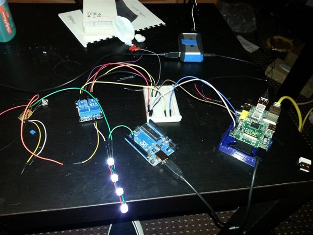
    I have taken a picture of the crude setup I have right now at my girlfriends house. Once I get home I will have another strip of 4 soldered up and then setup on my 3D printer to illuminate the bed. image


    image

    I apologise about the mess..


    My setup:


    My Raspberry Pi controls both an Arduino and an Opto-Isolated relay board.


    The purpose of this setup is so the Raspberry Pi can control a slave Arduino which sends the data to the LEDs and also switches the contacts on both channels of the relay board. The WS2812B chip +ve and -ve leads are attached to an external 5v 2A supply to prevent power problems. The power supply is fed through the relay so that the LEDs can be turned on and off via simple shell scripts executed on the Raspberry Pi. This setup is also useful because I can reprogram the Arduino through the Ino software package on the Raspberry Pi via the command line without the need for unplugging anything. This is the exact setup that I was after (though in a crude layout right now). The second relay on the relay board will be utilised as a shell controlled On/Off switch for my printer once I get home and find some 16A wire.

    • Cancel
    • Vote Up +2 Vote Down
    • Sign in to reply
    • Verify Answer
    • Cancel
element14 Community

element14 is the first online community specifically for engineers. Connect with your peers and get expert answers to your questions.

  • Members
  • Learn
  • Technologies
  • Challenges & Projects
  • Products
  • Store
  • About Us
  • Feedback & Support
  • FAQs
  • Terms of Use
  • Privacy Policy
  • Legal and Copyright Notices
  • Sitemap
  • Cookies

An Avnet Company © 2026 Premier Farnell Limited. All Rights Reserved.

Premier Farnell Ltd, registered in England and Wales (no 00876412), registered office: Farnell House, Forge Lane, Leeds LS12 2NE.

Follow element14

  • X
  • Facebook
  • linkedin
  • YouTube